Micro manipulator for movement of electrode, driving method thereof, and measuring device of brain signal using the same

a micro-manipulator and electrode technology, applied in the direction of generator/motor, diagnostic recording/measuring, surgery, etc., can solve the problems of reducing resolution and difficult to accurately position the electrode to the desired position from the brain neurons, and achieve the effect of improving distance resolution

Active Publication Date: 2008-12-16
KOREA INST OF SCI & TECH
View PDF8 Cites 3 Cited by
  • Summary
  • Abstract
  • Description
  • Claims
  • Application Information

AI Technical Summary

Benefits of technology

[0010]Accordingly, the present invention has been made to solve the above-mentioned problems occurring in the prior art, and an object of the present invention is to provide a micro manipulator for movement of an electrode capable of precisely positioning the electrode to a desired position from the brain neurons through the improvement of a distance resolution of the electrode approaching the brain neurons, a driving method thereof, and a brain signal measuring device using the same.

Problems solved by technology

Thus, in the conventional micro manipulator, with all precise manufacturing of the drive shaft, there is a limit to accurately regulate the electrode, so that the distance resolution is considerably reduced, causing a problem in that it is difficult to accurately position the electrode to a desired position from the brain neurons.

Method used


Image

  • Micro manipulator for movement of electrode, driving method thereof, and measuring device of brain signal using the same
  • Micro manipulator for movement of electrode, driving method thereof, and measuring device of brain signal using the same
  • Micro manipulator for movement of electrode, driving method thereof, and measuring device of brain signal using the same

Examples


Embodiment Construction

[0022]Hereinafter, preferred embodiments of the present invention will be described with reference to the accompanying drawings.

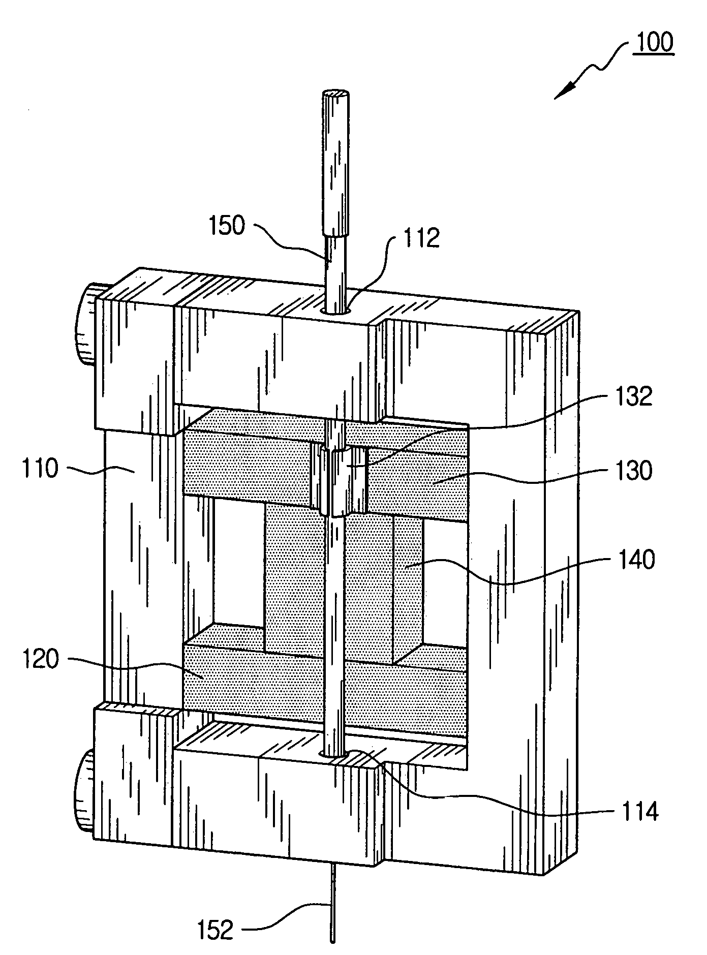
[0023]FIG. 3 is a perspective view of a micro manipulator 100 for the movement of an electrode according to a preferred embodiment of the present invention.

[0024]Referring to FIG. 3, the micro manipulator 100 for the movement of the electrode includes a guide member 110 having a rectangular hollow hole therein, first and second piezo-electric clamp bodies 120 and 130 installed perpendicular to the movement direction of the electrode 152 between the inner opposite sides in the hollow hole of the guide member 100, a drive piezo-electric body 140 whose both ends are connected to the opposite faces, respectively, of the first and second clamp piezo-electric bodies 120 and 130, and an electrode holder 150 holding therein the electrode 152 and installed on the first or second clamp piezo-electric body 120 or 130 in parallel with the drive piezo-electric body 140....


PUM


Abstract

A micro manipulator for electrode movement, a driving method thereof, and a brain signal measuring device using the same are provided. The micro manipulator has a guide member having a rectangular hollow hole therein, first and second piezo-electric clamp bodies installed perpendicular to the movement direction of the electrode between the inner opposite sides in the hollow hole of the guide member such that respective both ends thereof are selectively fixed to or separated from the inner sides of the hollow hole depending upon whether of the application of electric power thereto, a drive piezo-electric body whose both ends are connected to the opposite faces, respectively, of the first and second clamp piezo-electric bodies to selectively expand or contract in parallel with the movement direction of the electrode depending upon whether of the application of electric power thereto, and an electrode holder holding therein the electrode and installed on the first or second clamp piezo-electric body in parallel with the expansion or contraction direction of the drive piezo-electric body.

Description

BACKGROUND OF THE INVENTION[0001]1. Field of the Invention[0002]The present invention relates to a micro manipulator for moving an electrode, a driving method thereof, and a measuring device of a brain signal using the same, and more particularly to a micro manipulator capable of moving an electrode to a desired position through the more precise movement of the electrode approaching the cranial nerve cells, a driving method thereof, and a measuring device of a brain signal using the same.[0003]2. Description of the Prior Art[0004]Typically, there are approximately 1011 neurons in a brain of a human being, and the neurons transfer information by means of electric signals. For the analysis of a function of the neuron, there have been proposed analysis methods for analyzing an electrical characteristic of the brain neuron for an external stimulus, and a vital reaction under an electrical stimulus for specified brain neuron.[0005]A conventional measuring device for measuring a brain sig...

Claims


Application Information

Patent Timeline
Patent Type & Authority Patents(United States)
IPC IPC(8): H01L41/053H01L41/08H02N2/02
CPCA61B5/04001A61B5/6835A61B19/22A61B2019/2249A61N1/0529H02N2/023A61B2503/40A61B34/70A61B34/72A61B5/24A61B5/388
Inventor KIM, BYUNG-KYUPARK, SUK-HOSHIN, HEE-SUPKIM, DAE-SOOPARK, HYUN-JUNPARK, JONG-OH
Owner KOREA INST OF SCI & TECH
Why Eureka
Try Eureka