Radio frequency unit

a frequency unit and frequency technology, applied in the direction of casings/cabinets/drawers, continuous tuning, casings/cabinets/drawers, etc., can solve the problem of insufficient grounding of the wiring pattern, and achieve the effect of sufficient grounding

Inactive Publication Date: 2008-12-16
ALPS ALPINE CO LTD
View PDF13 Cites 15 Cited by
  • Summary
  • Abstract
  • Description
  • Claims
  • Application Information

AI Technical Summary

Benefits of technology

[0013]In the invention configured in this way, the insulating board is soldered to the tongue pieces of the supporting member bent from the front plate of the chassis. Therefore, even if a difference is caused in expansion or contraction between the chassis of a metallic material and the insulating board made of an insulating material under a use environment, the tongue pieces having a free end are moved to follow the expansion or contraction of the insulating board. As a result, sufficient grounding can be obtained without peeling-off of the solder between the tongue pieces and the insulating board. Also, the supporting member is located between inside the chassis between the two connectors. Therefore, when the two connectors are used for input, the grounding between the connectors inside the chassis becomes positive. As a result, excellent isolation is obtained between the connectors.
[0015]In the invention configured in this way, the tongue pieces are brought into resilient contact with the insulating board, so that the space between the tongue pieces and the insulating board can be removed, and the soldering between the tongue pieces and the insulating board can become good.
[0017]In the invention configured in this way, the provision of the shield plate that divides the inside of the chassis makes it possible to obtain excellent isolation between the connectors or between divided partition chambers.
[0020]According to the radio frequency unit of the invention, the insulating board is soldered to the tongue pieces of the supporting member bent from the front plate of the chassis. Therefore, even if a difference is caused in expansion or contraction between the chassis of a metallic material and the insulating board made of an insulating material under a use environment, the tongue pieces having a free end are moved to follow the expansion or contraction of the insulating board. As a result, sufficient grounding can be obtained without peeling-off of the solder between the tongue pieces and the insulating board.

Problems solved by technology

Therefore, due to a difference in expansion or contraction between the chassis 51 and the insulating board 58, there is a problem in that the solder 69 between the chassis 51 and the wiring pattern is peeled off, and grounding of the wiring pattern becomes insufficient.

Method used


Image

  • Radio frequency unit
  • Radio frequency unit
  • Radio frequency unit

Examples


Embodiment Construction

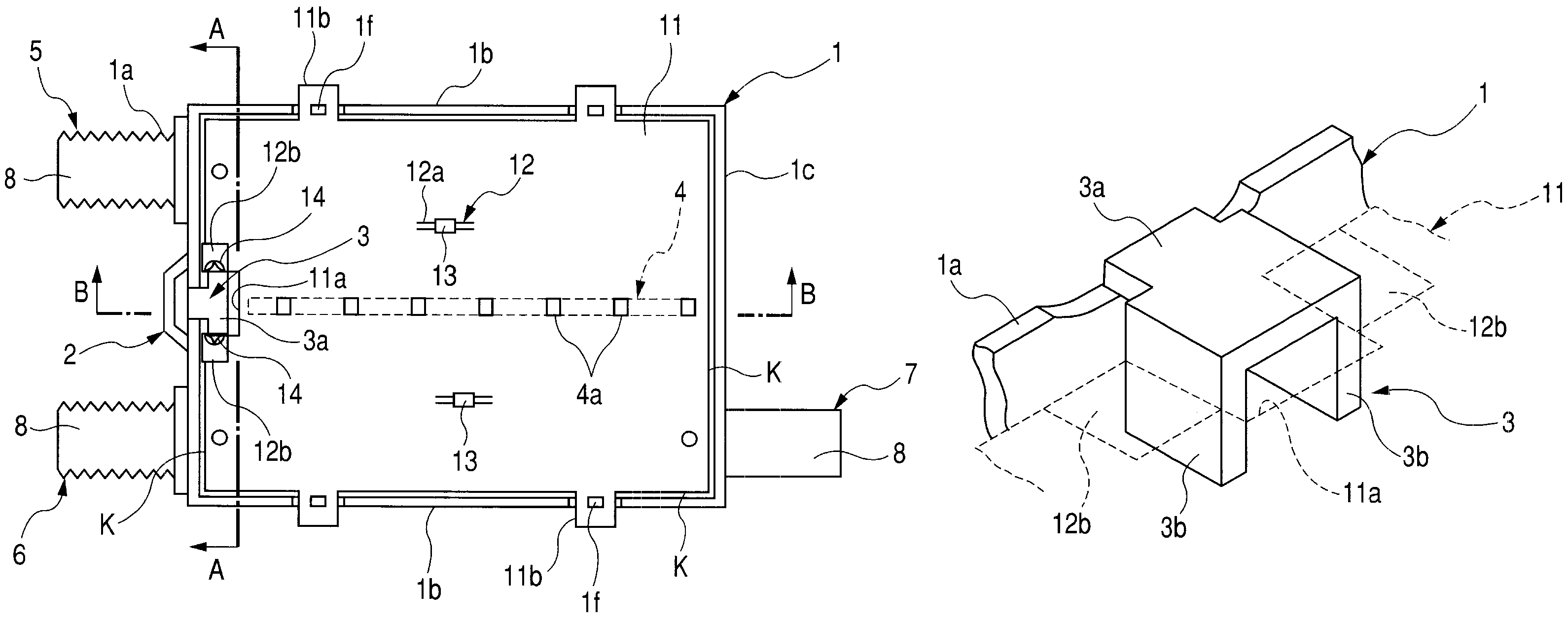
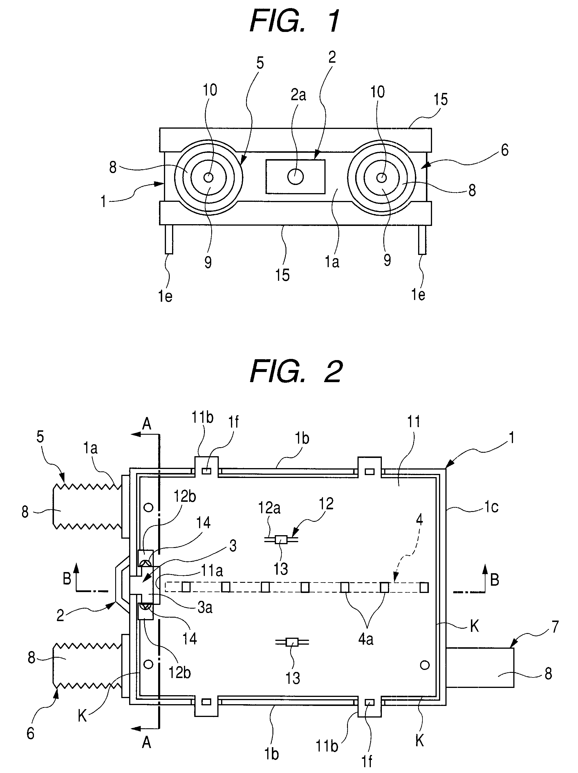
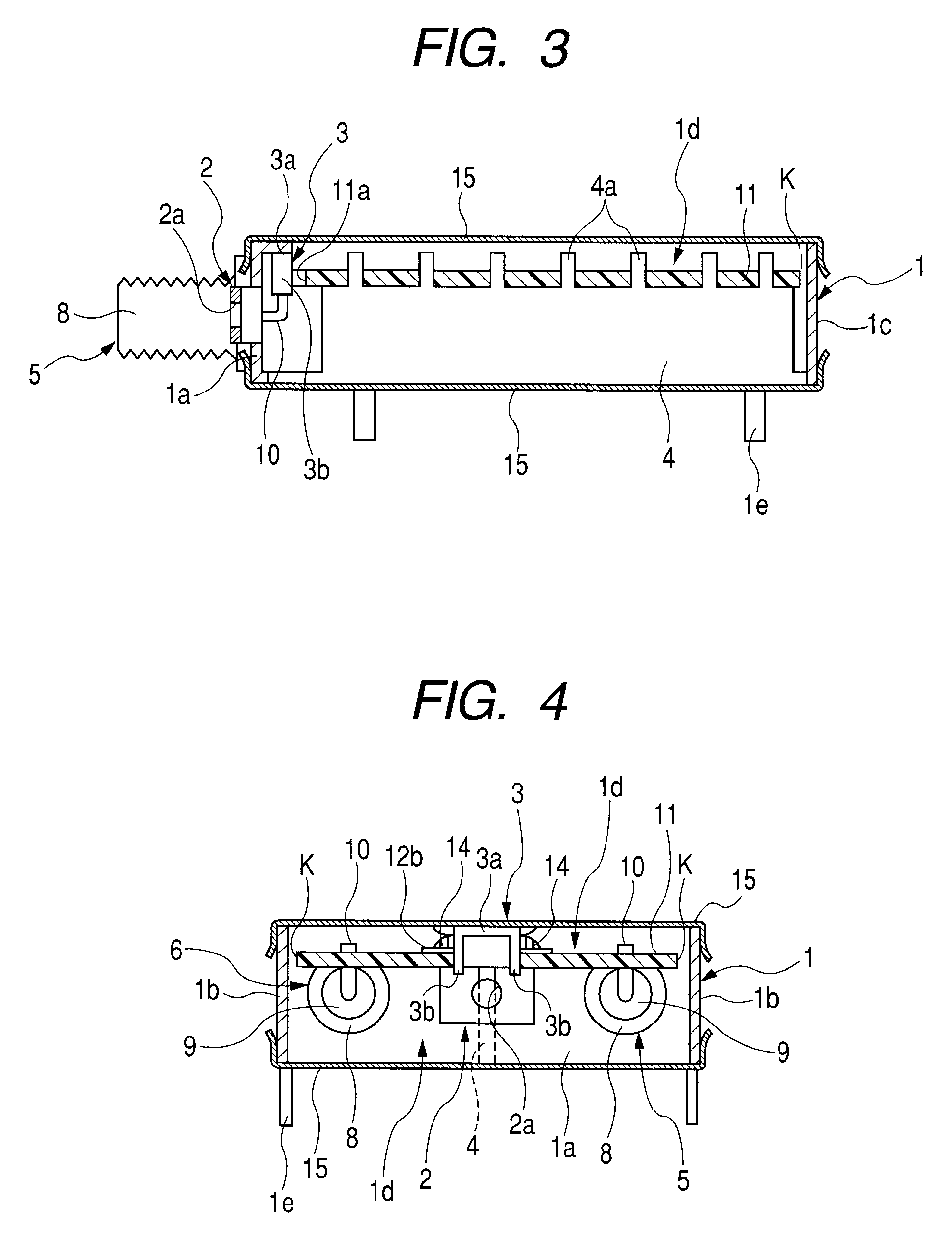
[0030]A preferred embodiment of the invention will now be described with reference to the drawings. FIG. 1 is a plan view of a radio frequency unit of the invention, FIG. 2 is a plan view the radio frequency unit of the invention in a state where a cover is removed, FIG. 3 is a sectional view taken along line A-A, FIG. 4 is a sectional view taken along line B-B, FIG. 5 is an enlarged perspective view showing portions of a supporting member relating to the radio frequency unit of the invention, FIG. 6 is a deployed view showing a method of forming the supporting member relating to the radio frequency unit of the invention, and FIG. 7 is an exploded view showing the method of forming the supporting member relating to the radio frequency unit of the invention.

[0031]Next, the configuration of the radio frequency unit of the invention will now be described with reference to FIGS. 1 to 7. A box-shaped chassis 1 made of a metal plate includes an oblong front plate 1a, a pair of side plates...


PUM


Abstract

The invention provides a radio frequency unit including a box-shaped chassis into which an insulating board loaded with electronic components is housed, and two connectors attached to a front plate of the chassis with a space therebetween. A supporting member protruding into the chassis is provided in a position between the two connectors in the front plate. The supporting member has a flat plate portion that is bent at right angles from an end face of the front plate, and extends parallel to the insulating board, and a pair of tongue pieces that are formed so as to be bent towards the inside of the chassis from both side ends of the flat plate portion. The pair of tongue pieces are located in a cutout portion provided in the insulating board, and the tongue pieces are soldered to a grounding pattern provided in the insulating board.

Description

BACKGROUND OF THE INVENTION[0001]1. Field of the Invention[0002]The present invention relates to a radio frequency unit suitable to be applied to an RF switch, etc. that is used for a television receiver.[0003]2. Description of the Related Art[0004]FIG. 8 is a perspective view of a conventional radio frequency unit, and FIG. 9 is a sectional view taken along C-C of the invention. Next, the configuration of the conventional radio frequency unit will now be described with reference to FIGS. 8 and 9. A box-shaped chassis 51 made of a metal plate includes a front plate 51a, top and bottom plates 51b and 51c bent rearward from the top and bottom positions of the front plate 51a, a rear plate 51d provided between the top and bottom plates 51b and 51c, a side plate 51e that blocks up one side face of the chassis 51, an open portion 51f provided at the other side face of the chassis 51, a plurality of downwardly extending attachment legs 51g, and an attachment portion 51j provided at the fr...

Claims


Application Information

Patent Timeline
Patent Type & Authority Patents(United States)
IPC IPC(8): H05K9/00
CPCH04B1/18H05K1/0213H05K3/3405
Inventor HARADA, KEIKOYOTSUGURI, SATOSHI
Owner ALPS ALPINE CO LTD
Why Eureka
Try Eureka