

Method and apparatus for positioning a center of a seismic source
a technology of seismic source and center, applied in seismology, seismology, instruments, etc., can solve the problems of less than perfectly linear sail lines, limited accuracy and/or resolution of the representation formed using acquired data, and rarely, if ever, the exact sail line of the center of the sour
- Summary
- Abstract
- Description
- Claims
- Application Information
AI Technical Summary
Benefits of technology
Problems solved by technology
Method used
Image

Examples
first embodiment
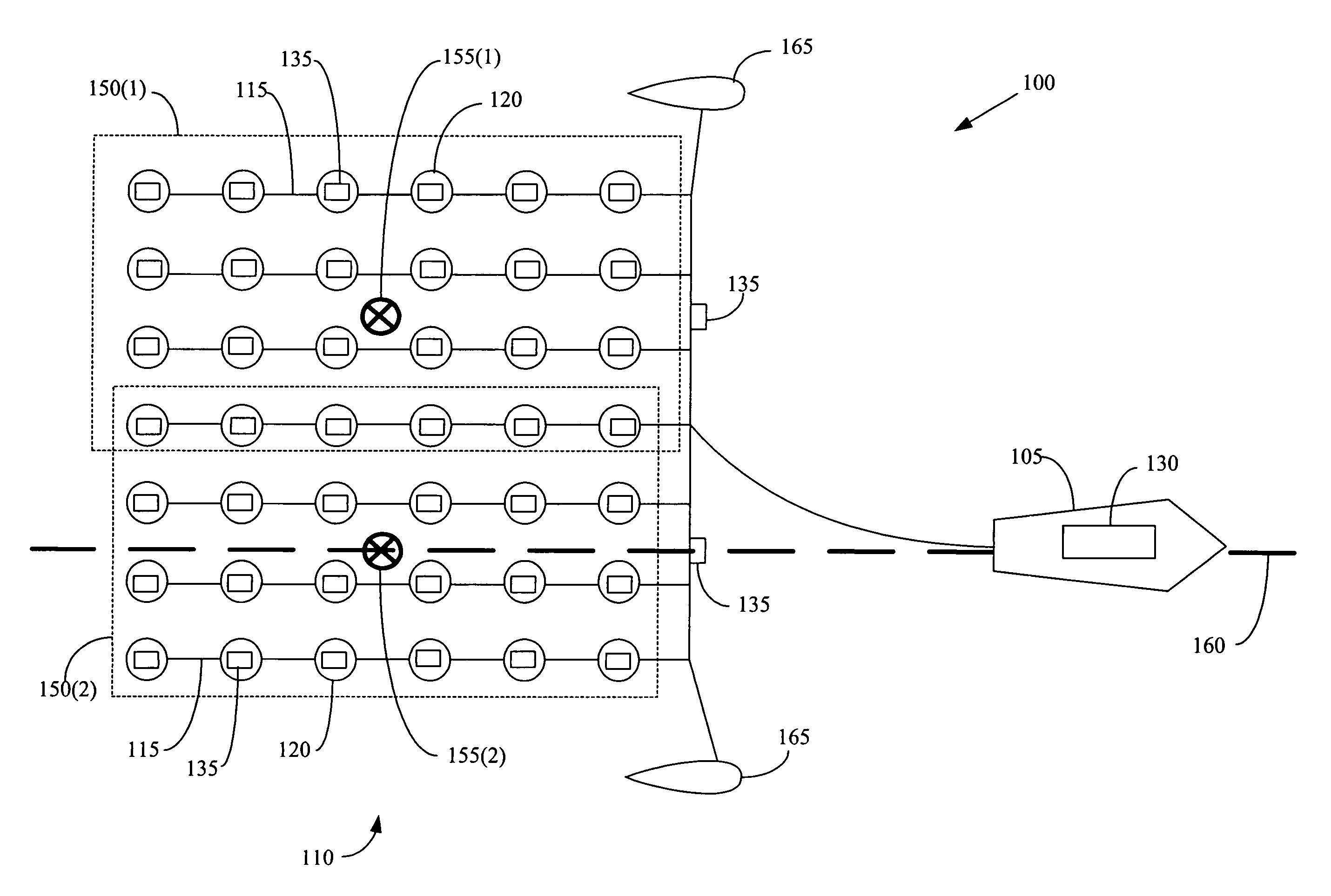
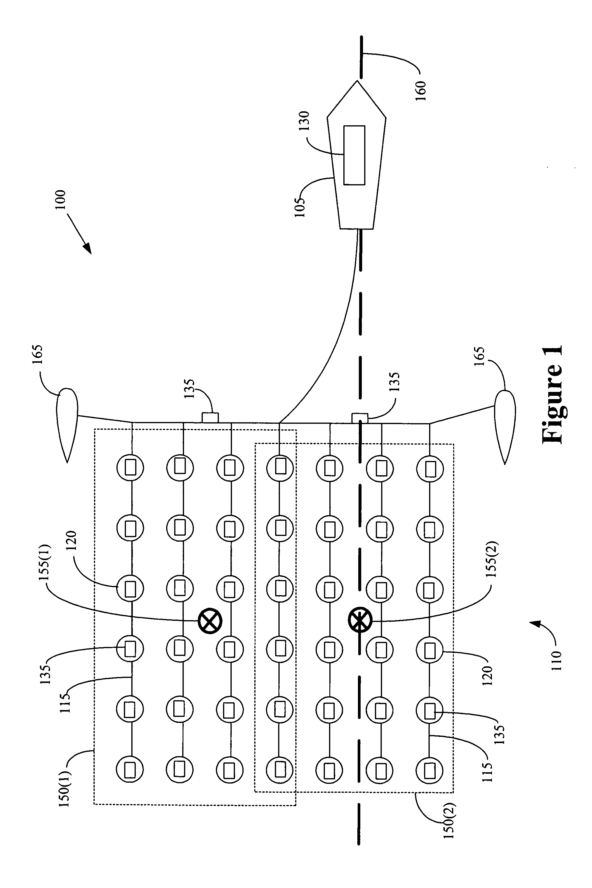
[0021]FIG. 1 conceptually illustrates a system 100 for providing seismic shots. The system 100 includes a survey vessel 105 coupled to a gun array 110 formed of a plurality of cables 115 having a plurality of guns 120, such as airguns and the like, attached thereto. The gun array 110 shown in FIG. 1 is a two-dimensional array. However, in alternative embodiments such as described below, the gun array 110 may also be one-dimensional or three-dimensional. Persons of ordinary skill in the art should also appreciate that, in alternative embodiments, the system 100 may also include a plurality of seismic receivers (not shown). For example, the survey vessel 105 may tow an array of seismic receivers (not shown). Alternatively, the seismic receivers (not shown) may be towed by another survey vessel, or they may be deployed on the sea bed, in a borehole, or in any other desirable location.
[0022]In the illustrated embodiment, the gun array 110 includes seven cables 115. However, the present ...
second embodiment
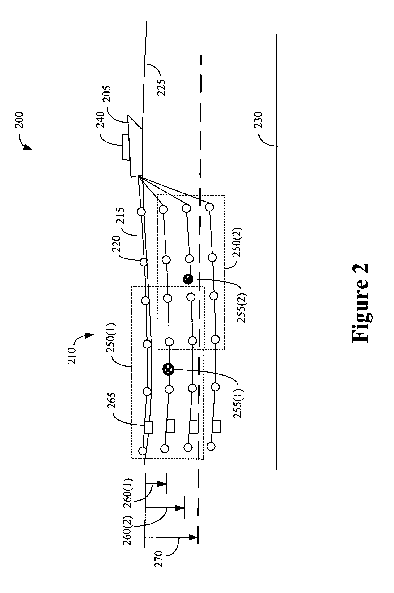
[0037]FIG. 2 conceptually illustrates a system 200 for providing a seismic shot. In the system 200, the groupings of guns differ vertically, rather than horizontally. The system 200 includes a survey vessel 205 coupled to a gun array 210 comprising a plurality of cables 215 having a plurality of guns 220, such as airguns and the like, attached thereto. The plurality of cables 215 are deployed at different depths beneath the surface 225 of a body of water and heights above the floor 230 of the body of water. Although a plurality of cables 215 a shown in FIG. 2, in one alternative embodiment, a single cable 215 having a plurality of guns 220 suspended at different depths below the cable 215 may be used.
[0038]In the illustrated embodiment, the system 200 is a two-dimensional gun array 210 oriented in an approximately vertical plane. However, in alternative embodiments, the system 200 may also be a portion of a three-dimensional gun array. Although not shown in FIG. 2, in one alternativ...
third embodiment
[0043]FIGS. 3A and 3B conceptually illustrate a system 300 for providing a seismic shot. The system 300 includes a survey vessel 305, which is coupled to a gun array 310 formed using a plurality of cables 315 having a plurality of guns 320 attached thereto. As discussed above, each of the plurality of guns 320 are communicatively coupled to a controller 325, which is capable of providing one or more signals to selected portions of the plurality of guns 320 that may be used to initiate one or more seismic shots from the guns 320 in the selected portions. In various alternative embodiments, one or more positioning devices 330 are deployed proximate the guns 320 and / or along one or more of the cables 315. The positioning devices 330 provide information indicative of their position to the controller 325.
[0044]In the third embodiment of the system 300, the controller 325 may select a configuration of guns 320 arranged in a predetermined pattern to form a first seismic source 335, as show...
PUM
 Abstract
Description
Claims
Application Information