Method and apparatus for image compression and decompression

a compression and decompression technology, applied in the field of image compression/decompression, can solve the problems of slowing down the performance of compression, increasing the cost of reference memory buffer and on-chip searching range buffer, and consuming high bandwidth of i/o bus, so as to reduce the required amount of storage devices

Active Publication Date: 2008-12-16
TAIWAN IMAGINGTEK
View PDF7 Cites 15 Cited by
  • Summary
  • Abstract
  • Description
  • Claims
  • Application Information

AI Technical Summary

Benefits of technology

[0010]The present invention is related to a method and apparatus of the reference image buffer compression, which plays an important role in image compression, specifically in compressing the referencing frame buffer for the motion video compression. The present invention significantly reduces required storage device density and accessing bandwidth of the referencing image.
[0021]According to an embodiment of the present invention of the reference image compression, the distribution of truncating bits will not start from the same position hence avoid accumulation of error over time.
[0024]According to an embodiment of the present invention of the reference image compression, adaptively change the block size from block to block is applied to achieve higher performance and still maintain high compression rate and good quality.
[0025]According to an embodiment of the present invention of the reference image compression, double hardware of encoder and decoder are proposed in this invention for further enhance the performance of encoding and decoding with reduced latency time in recovering the 1st pixels and a block of pixels.

Problems solved by technology

Transporting pixels between a video encoder or decoder chip and the memory buffer consumes high bandwidth of the I / O bus of memory storing the frame buffers.
In summary, due to the need of reference memory buffer of previous and future frames and the need of a image buffer for temporarily storing the pixels of searching range, the cost of the reference memory buffer and on-chip searching range buffer are increasingly large with the increase of image resolution.
From the bandwidth point view, the frequent accessing the mass image data consumes high power and causes I / O traffic jam which usually slow down the performance of compression and some times degrade the quality of image.

Method used


Image

  • Method and apparatus for image compression and decompression
  • Method and apparatus for image compression and decompression
  • Method and apparatus for image compression and decompression

Examples


Embodiment Construction

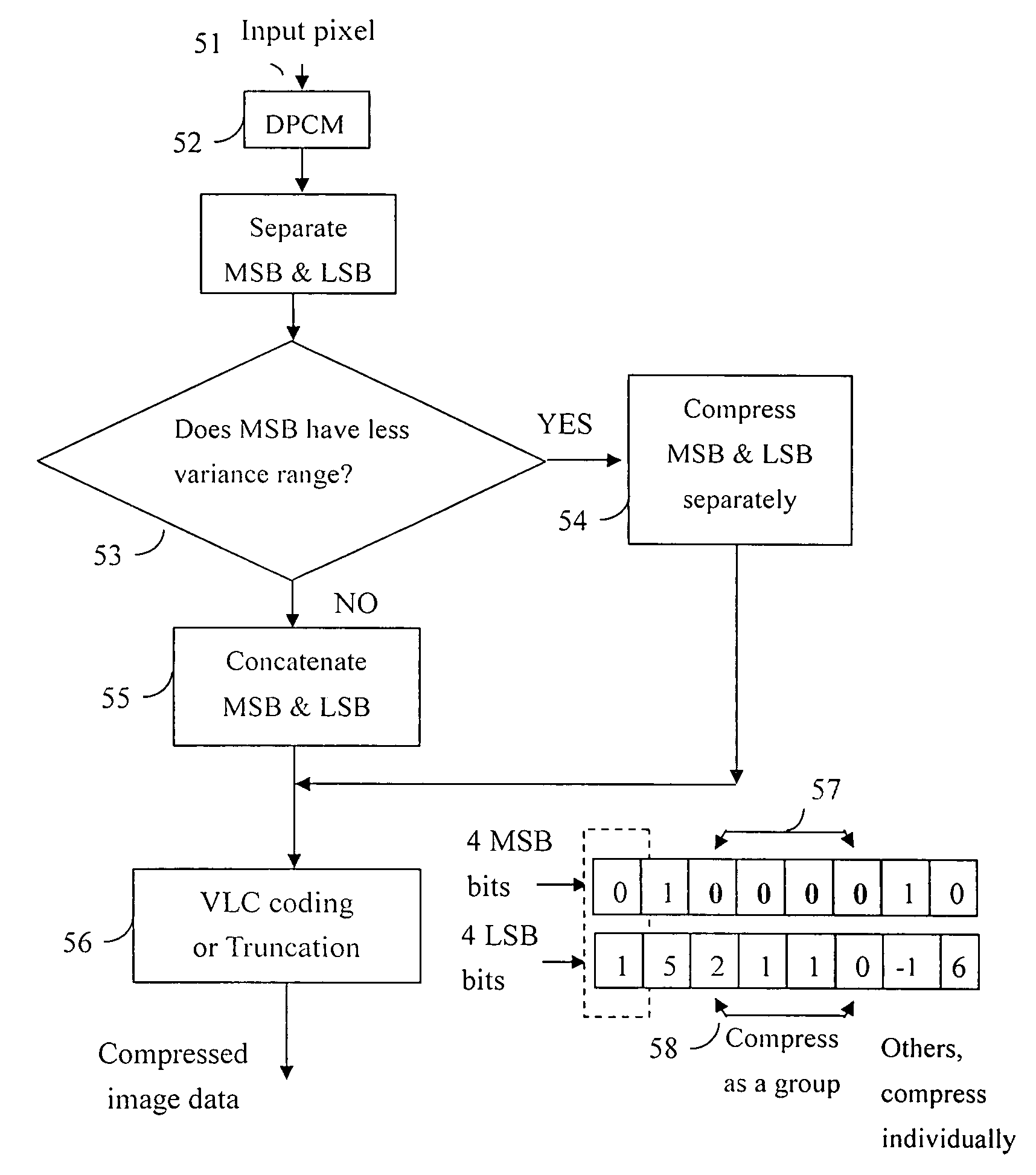
[0042]In a preferred embodiment according to the present invention, an image compression method for compressing groups of pixel data includes steps of compressing MSB (most significant bits) portions and LSB (least significant bits) portions of each group of pixel data separately. If a pixel data is composed of 8 bits, an example of the MSB portion is the left four bits and the LSB portion is the right four bits. However, the MSB portion may be defined as left five or other number of bits and the LSB portion is the rest bits. Adopting this step would enhance compression ratio because there is a nature that MSB portion usually have more resemblance comparing with LSB portions. The pixel data can be raw pixel information or data processed after quantization, DCT, and / or obtained by subtracting a reference value from raw pixel information.

[0043]In addition, the LSB portions are grouped according their associated MSB portions so that different compression methods, e.g. variable-length c...


PUM


Abstract

An image compression method for compressing groups of pixel data, including the following steps: MSB portions and LSB portions of the pixel data are compressed separately. Further, the LSB portions are grouped according to their associated MSB portions so that similar pixels are compressed together to gain higher a compression ratio. Some LSB portions are truncated to ensure a compression ratio. When performing compression, enhanced variable-length coding is adopted that predicts more accurate dividers by considering weighted combination of adjacent pixels. The quotient of each groups of compression portion is predicted and coded accordingly.

Description

BACKGROUND OF THE INVENTION[0001]1. Field of Invention[0002]The present invention relates to image compression / decompression, and more particularly relates to the reference image compression / decompression for achieving a predetermined compression ratio.[0003]2. Description of Related Art[0004]Digital image and motion video have been adopted in an increasing number of applications, which include digital camera, scanner / printer / fax machine, video telephony, videoconferencing, surveillance system, VCD (Video CD), DVD, digital TV . . . etc. In the past decades, ISO and ITU have separately or jointly developed and defined some digital video compression standards including JPEG, JPEG2000, JBIG, MPEG-1, MPEG-2, MPEG-4, MPEG-7, H.261, H.263 and H.264. The success of development of the still image and video compression standards fuels wider applications. The advantage of image and video compression techniques significantly saves the storage space and transmission time without sacrificing muc...

Claims


Application Information

Patent Timeline
Patent Type & Authority Patents(United States)
IPC IPC(8): G06K9/00G06K9/36G06K9/46H03M7/40H04N1/413H04N11/02H04N11/04H04N7/12
CPCH04N19/61H04N19/103H04N19/90H04N19/184H04N19/428H04N19/136
Inventor SUNG, CHIH-TA STARCHENG, CHIH-SHENGLAN, YIN-CHUN
Owner TAIWAN IMAGINGTEK
Why Eureka
Try Eureka