Method of controlling a feeler to read the bezel of an eyeglass frame

a technology of eyeglass frames and feelers, which is applied in the field of eyeglasses, can solve the problems of the feeler not being able to accurately follow the bottom of the v-shaped bezel, the risk of the feeler escaping from the bezel by sliding along the side surface, and the curvature of the path followed by the feeler along a first axis

Active Publication Date: 2008-12-23
ESSILOR INT CIE GEN DOPTIQUE
View PDF8 Cites 11 Cited by
  • Summary
  • Abstract
  • Description
  • Claims
  • Application Information

AI Technical Summary

Benefits of technology

[0015]In order to remedy the above-mentioned drawback in the state of the art, the present invention proposes a simple method of reading the outline of a bezel that enables the bottom of the bezel to be read accurately.
[0017]Thus, by means of the invention, starting from a sample of typical frames, it is possible to define positions of the feeler along the first axis that are characteristic of eyeglass frames and from which it is necessary to vary the forces exerted by the feeler against the bezel of the frame being felt. These values are thus defined and remain the same regardless of the frame that is placed in the outline reader appliance, and regardless of whether or not the frame is very cambered. Furthermore, the feeler is controlled in force and not in position. The appliance can thus be set quickly and easily.
[0020]Thus, the actuator means are suitable for exerting a force that enables the feeler to be constrained to remain at the bottom of the bezel. The transverse component of the overall force is a conventional component that makes it possible, so long as the V-shaped bezel is not “skewed”, for the feeler to slide over either of the side surfaces of the V-shape of the bezel towards the bottom of the bezel and to remain there. The axial component of the force serves at least to cancel the weight of the feeler when the feeler is vertical. It also enables the feeler to be “pushed” towards the bottom of the bezel when the bezel is strongly “skewed” and one of the side surfaces of its V-shape is inclined too steeply to enable a transverse force on its own to cause the feeler to slide along the bottom of the bezel.
[0022]It is thus possible to cause the two components of the overall force to vary independently in such a manner that the overall force presents a value and a direction that are optimized as a function of the “skew” and of the camber of the frame.
[0024]Advantageously, for the eyeglass frame having an inside that is to be positioned facing the eyes of the wearer, the value of the position of the feeler along the first axis increases with the feeler going towards the inside of the frame, the value of the axial component of the overall force growing continuously or in steps, while the value of the position of the feeler increases.
[0027]Thus, when the overall force in particular varies in steps as a function of the position of the feeler about the axis of rotation, it is possible to cause both the axial and the transverse components of the force to vary continuously as a function of the angular position of the feeler. This smoothing of the overall force then makes it possible to cause the overall force to vary in closer compliance with the “skew” of the frame.

Problems solved by technology

For frames that are strongly “curved” and “skewed”, i.e. strongly cambered and twisted, merely pressing the feeler against the bezel orthogonally to the axis of rotation of the feeler does not enable the feeler to follow the bottom of the V-shaped bezel accurately.
In particular, when the “skew” or twisting of the frame is very considerable, and one of the side faces of the bezel is steeply inclined, then there is a risk of the feeler escaping from the bezel by sliding along that side surface.
The drawback of such a device is that in certain portions of the rim of the frame, and in particular in its temple portions, the curvature of the path followed by the feeler along a first axis (normal to the general plane of the rims of the frame) is not large, unlike the skew of the frame.
As a result, in certain portions of the rim, the control over the position of the feeler does not respond effectively to the skew of the frame.

Method used


Image

  • Method of controlling a feeler to read the bezel of an eyeglass frame
  • Method of controlling a feeler to read the bezel of an eyeglass frame
  • Method of controlling a feeler to read the bezel of an eyeglass frame

Examples


Embodiment Construction

[0030]The following description with reference to the accompanying drawings that are given by way of non-limiting example makes it clear what the invention consists in and how it can be implemented.

[0031]In the accompanying drawings:

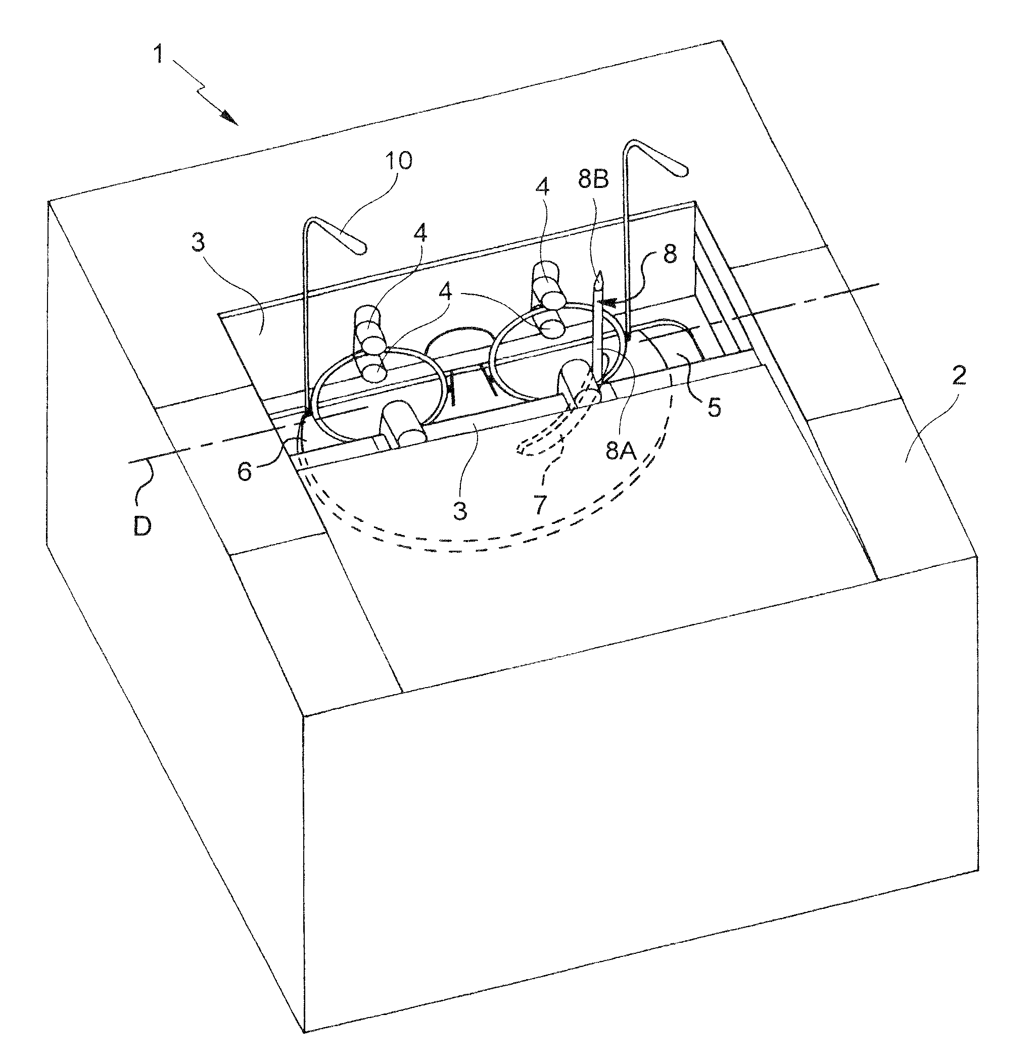
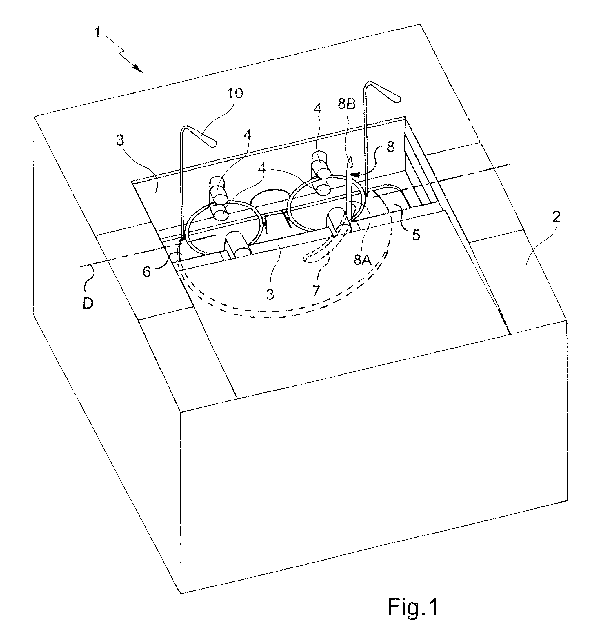
[0032]FIG. 1 is a perspective view of an outline reader appliance receiving an eyeglass frame from which the shapes of the rims are to be read by a feeler;

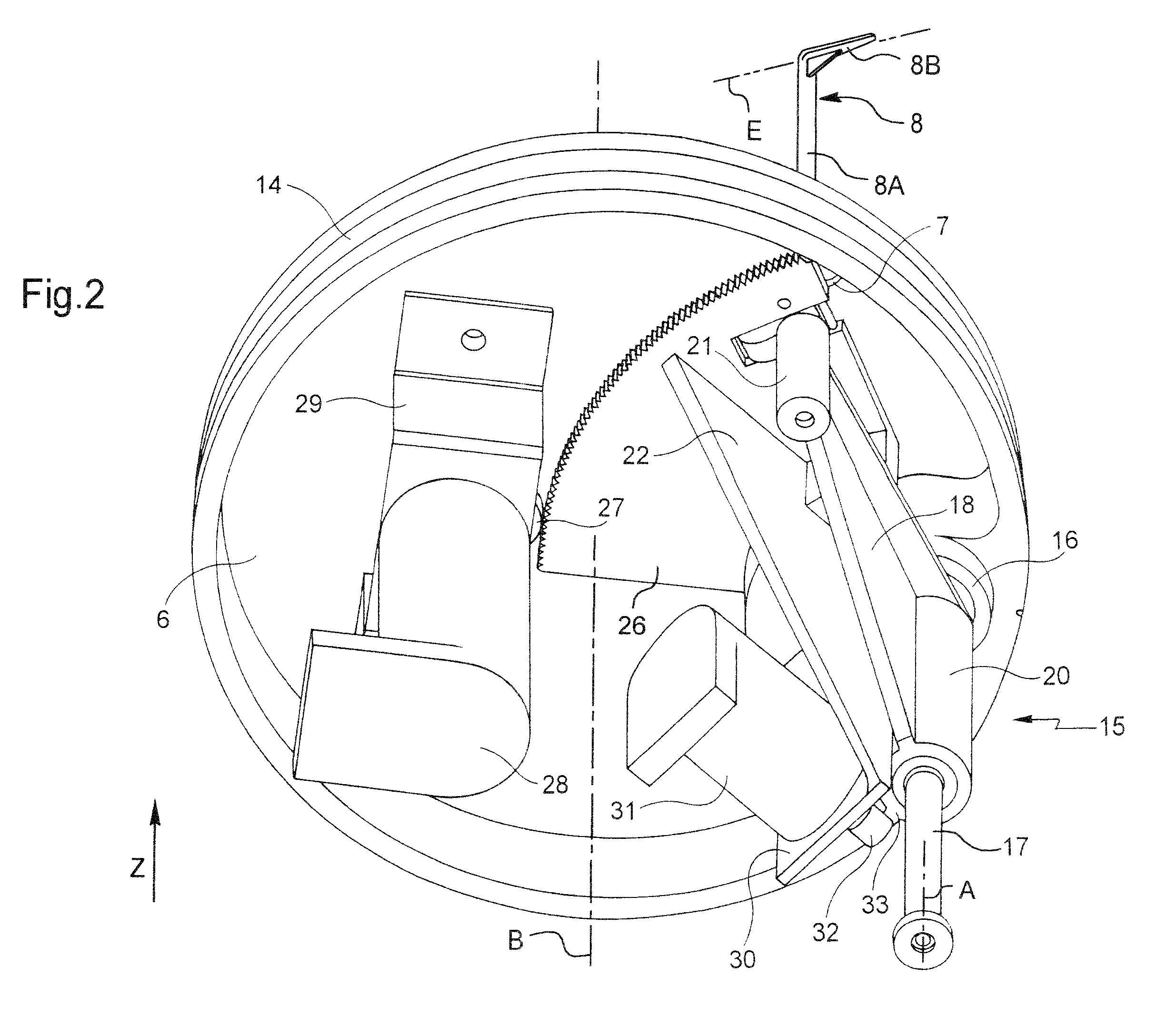
[0033]FIGS. 2 and 3 are perspective views of the underside of the turntable taken from the FIG. 1 appliance, these FIGS. 2 and 3 showing the reader subassembly carried by the turntable as viewed from two different angles;

[0034]FIG. 4 is a section view of the rims of shape that is read by the feeler;

[0035]FIG. 5 is a plan view of the eyeglass frame showing the camber of each of the rims; and

[0036]FIGS. 6A and 6B are section views of the bezel of a rim, at two points around its outline.

[0037]FIG. 1 is a general view of an outline reader appliance 1 as it appears to its user. This appliance includes a top...


PUM


Abstract

A method of reading the outline of the bezel of a rim of an eyeglass frame, includes the steps of putting a feeler into contact against the bezel and of feeling the bezel by sliding or running the feeler along the bezel, the feeler being actuated by actuator elements along at least a first axis normal to the general plane of the rims of the frame. According to the invention, the overall force delivered by the actuator elements varies continuously or in step during reading as a function of the position of the feeler along the first axis.

Description

TECHNICAL FIELD TO WHICH THE INVENTION RELATES[0001]The present invention relates in general to the field of eyeglasses and more precisely to feeling the bezel of a frame for rimmed eyeglasses.[0002]The invention relates more particularly to a method of reading the outline of the bezel of a rim of an eyeglass frame, the method comprising the steps of putting a feeler into contact against the bezel and of feeling the bezel by sliding or running said feeler along the bezel, the feeler being actuated by actuator means along at least a first axis normal to the general plane of the rims of the frame.[0003]The method finds a particularly advantageous application when used with eyeglasses that have frames that are strongly cambered, i.e. strongly curved.TECHNOLOGICAL BACKGROUND[0004]The technical portion of the work performed by an optician consists in mounting a pair of ophthalmic lenses in a frame selected by a wearer. Such mounting is made up of five main operations:[0005]reading the ou...

Claims


Application Information

Patent Timeline
Patent Type & Authority Patents(United States)
IPC IPC(8): A61B3/11
CPCB24B9/144B24B9/14G02C13/00
Inventor JACQ, FRANCIS
Owner ESSILOR INT CIE GEN DOPTIQUE
Why Eureka
Try Eureka