Connector

a technology of engagement lock and connector, which is applied in the direction of connection, electrical apparatus, coupling device connection, etc., can solve problems such as deformation or breakage, and achieve the effects of preventing breakage of the lock arm, avoiding any hindrance, and being easy to produ

Inactive Publication Date: 2008-12-23
SMK CORP
View PDF4 Cites 10 Cited by
  • Summary
  • Abstract
  • Description
  • Claims
  • Application Information

AI Technical Summary

Benefits of technology

[0010]The lock arm may be easily produced through injection molding of resin by forming a base part on the outer periphery of the connector housing of one of the connectors mentioned above. This base part has a lock arm that extends in an engagement direction with the other connector, a specified space on the outer side of this lock arm, and an arm protection part that extends for a specified length along this lock arm.
[0011]Here, the reason for having an arm protection part that extends for a specified length is not because of any need for conforming to the length of the lock arm. Any length is suitable that avoids any hindrance with the lock receiver, and that allows the arm...

Problems solved by technology

Here, the reason for equipping the connector having a flexible lock arm with an arm protection part is that the bend...

Method used


Image

  • Connector
  • Connector
  • Connector

Examples


Embodiment Construction

[0021]The following listing provides a key to the reference numerals and elements depicted in the drawings:

[0022]

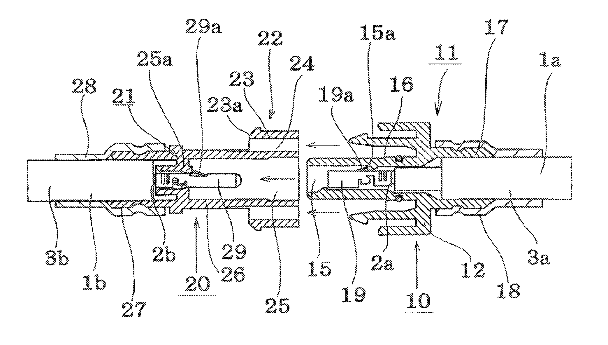
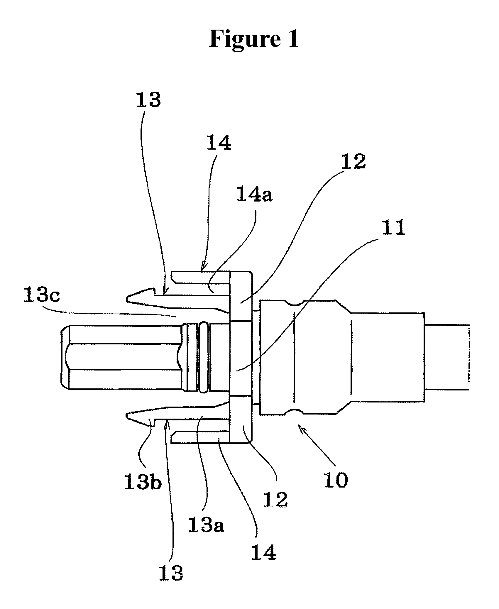
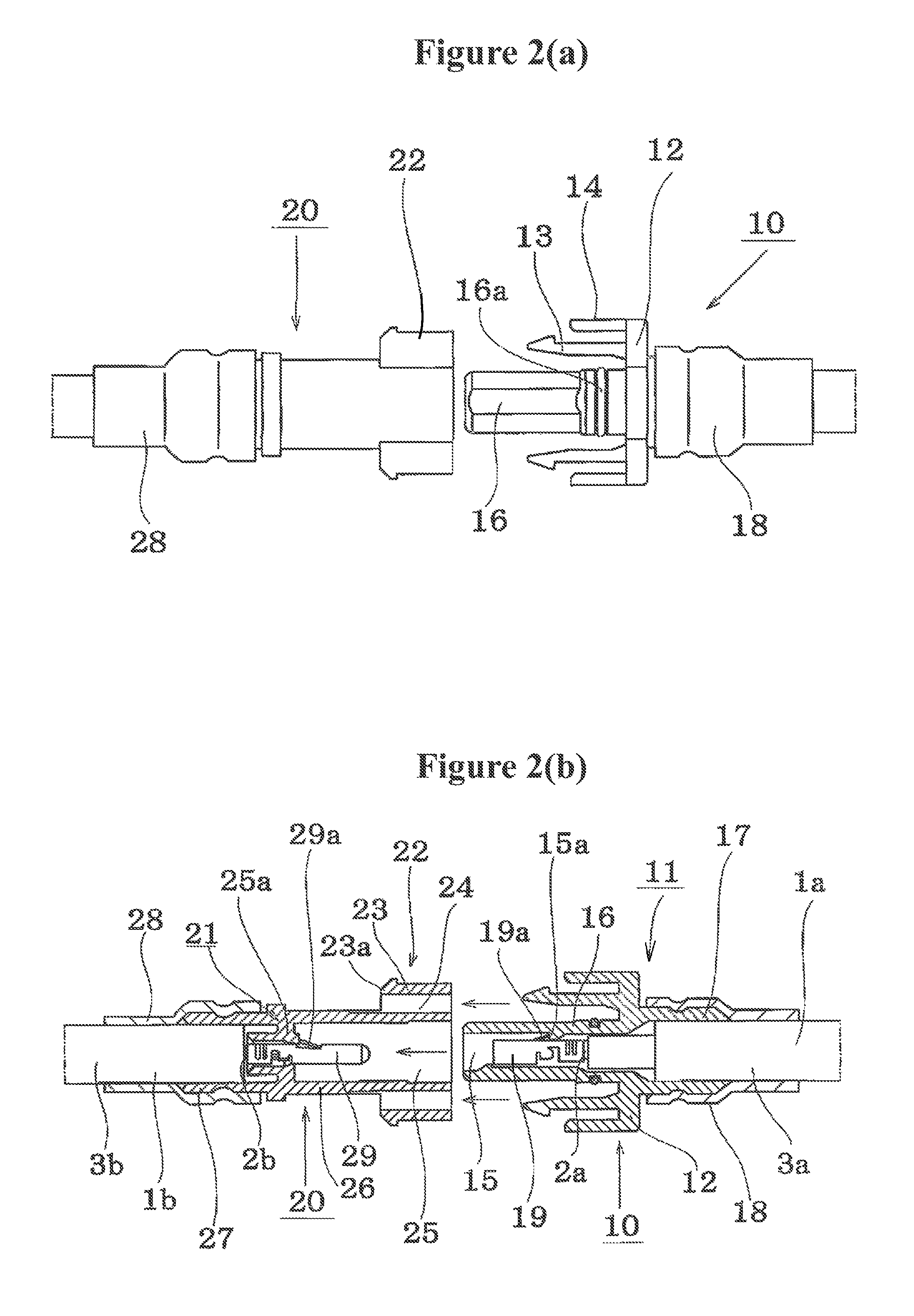
1a, 1b:Electric lines2a, 2b:Core wires3a, 3b:Cover parts10:Socket connector11:Socket connector housing12:Base part13:Lock arm13a:Flexible arm part13b:Linking catch13c:Arm bending space part14:Arm protection part14a:Insertion space15:Terminal storage chamber15a:Lance clip part16:Cylindrical engagement part16a:O-ring17:Cylindrical insertion part18:Contracting tube19:Socket terminal19aLance20:Plug connector21:Plug connector housing22:Lock receiver23:Linking part23a:Linking end24:Arm insertion hole25:Terminal storage chamber25a:Lance clip part26:Cylindrical engagement part27:Cylindrical insertion part28:Contracting tube29:Plug terminal29a:Lance

[0023]FIG. 1 shows an embodiment of a connector construction according to the present invention as applied to a socket connector.

[0024]Further, FIG. 2(a) is a external view of a socket connector 10 and plug connector 20 prior to engagem...


PUM


Abstract

A connector assembly making an electrical connection through the mutual engagement of a pair of connectors. One of the connectors has a flexible lock arm, and the other connector has a lock receiver that links to this lock arm. The connector that has the lock arm also has an arm protection part that extends over a substantial portion of an outer surface of the lock arm.

Description

CROSS-REFERENCE TO RELATED APPLICATION[0001]The present application claims priority from Japanese Patent Application No. 2007-203656, which was filed on Aug. 3, 2007 and is hereby incorporated by reference in its entirety herein.FIELD OF THE INVENTION[0002]The present invention relates to an engagement lock structure for a connector that provides an electrical connection through the mutual engagement of a pair of connectors.BACKGROUND OF THE INVENTION[0003]For example, as is shown in FIG. 4(a), one connector 110 belonging to a pair of conventional electrical connectors that are mutually engaged is equipped with a flexible lock arm 113, while the other connector 120 is equipped with a lock receiver 122. As shown in FIG. 4(b), the lock arm 113 is elastically linked to the lock receiver, such that the connectors are locked in an engaged position.[0004]However, the lock arm 113 prior to the connector engagement is such that it protrudes from the outer periphery of the connector housing ...

Claims


Application Information

Patent Timeline
IPC IPC(8): H01R13/627
CPCH01R13/6273
Inventor ARAI, ATSUSHI
Owner SMK CORP
Why Eureka
Try Eureka