Balanced splitter

a splitter and balanced technology, applied in the field of balanced splitters, can solve the problems of high manufacturing cost, increase in the number of components, and complex internal circuit configuration of components, and achieve the effect of simple miniaturized circuit configuration

Active Publication Date: 2008-12-23
MURATA MFG CO LTD
View PDF28 Cites 41 Cited by
  • Summary
  • Abstract
  • Description
  • Claims
  • Application Information

AI Technical Summary

Benefits of technology

[0009]In order to overcome the problems described above, preferred embodiments of the present invention provide a balanced splitter having a simple miniaturized circuit configuration.
[0016]Further, in a balanced splitter according to the above preferred embodiments, first, second, third, fourth, fifth, and sixth strip lines, and ground electrodes are laminated on top of one another through intermediate dielectric layers to define a laminate; and an unbalanced terminal, a first balanced terminal and a second balanced terminal, and a ground terminal are extended to a surface of the laminate, the first balanced terminal and the second balanced terminal each including two terminals; the unbalanced terminal is electrically connected to the first strip line of an unbalanced line including the first strip line and the second strip line that are connected in series; first and second of the first balanced terminals are electrically connected to the third strip line and the fourth strip line of a first balanced line, respectively, the first balanced line including the third strip line electromagnetically coupled to the first strip line, and the fourth strip line electromagnetically coupled to the second strip line; the first and second of the second balanced terminals are electrically connected to the fifth strip line and the sixth strip line of a second balanced line, respectively, the second balanced line including the fifth strip line electromagnetically coupled to the first strip line, and the sixth strip line electromagnetically coupled to the second strip line; a first resistor is electrically connected between the first balanced terminal connected to the third strip line and the second balanced terminal connected to the fifth strip line; and a second resistor is electrically connected between the first balanced terminal connected to the fourth strip line and the second balanced terminal connected to the sixth strip line. With the above-described construction, a laminated balanced splitter can be easily obtained.
[0019]According to the present preferred embodiments, the internal circuit configuration of the components is simplified, thereby making it possible to obtain a compact balanced splitter having low manufacturing cost and small insertion loss.

Problems solved by technology

However, when the balanced splitter 1 is constructed by combining the splitter 2 and the baluns 3, 4, each of which are separate components, a problem arises in that the number of components increases.
Further, as shown in FIG. 14, when the separate components 2 to 4 are simply integrated into one component, the internal circuit configuration of the component becomes rather complex leading to such problems as high manufacturing cost and large insertion loss.

Method used


Image

  • Balanced splitter
  • Balanced splitter
  • Balanced splitter

Examples


embodiment 1

Preferred Embodiment 1

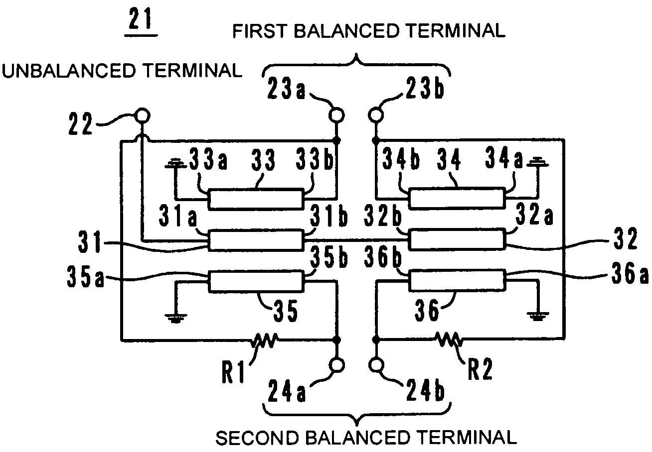
[0036]As shown in FIG. 1, a balanced splitter 21 has ¼ strip lines 31, 32, 33, 34, 35, 36. Each of the strip lines 31, 32, 33, 34, 35, 36 has first end 31a, 32a, 33a, 34a, 35a, 36a and second end 31b, 32b, 33b, 34b, 35b, 36b, respectively. The first end 31a of the strip line 31 is electrically connected to an unbalanced terminal 22, and the second end thereof 31b is electrically connected to the second end 32b of the strip line 32. The first end 32a of the strip line 32 is an open end. The first end 33a of the strip line 33 is grounded, and the second end 33b thereof is electrically connected to a first balanced terminal 23a. The first end 34a of the strip line 34 is grounded, and the second end 34b thereof is electrically connected to a first balanced terminal 23b. The first end 35a of the strip line 35 is grounded, and the second end 35b thereof is electrically connected to a second balanced terminal 24a. The first end 36a of the strip line 36 is grounded, an...

embodiment 2

Preferred Embodiment 2

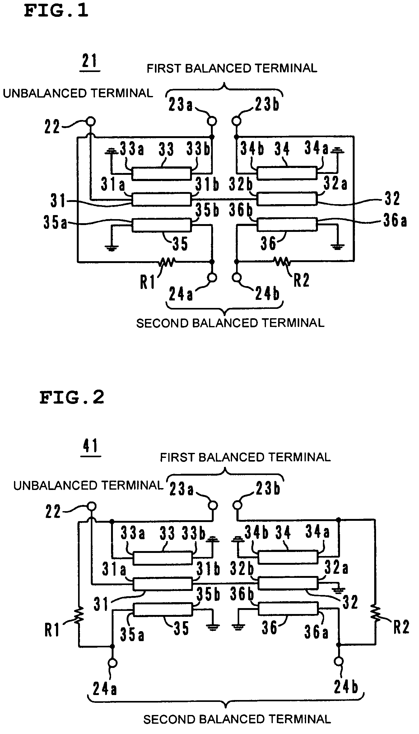
[0043]As shown in FIG. 2, a balanced splitter 41 includes ¼ strip lines 31, 32, 33, 34, 35, 36. Each of the strip lines 31, 32, 33, 34, 35, 36 has a first end 31a, 32a, 33a, 34a, 35a, 36a and a second end 31b, 32b, 33b, 34b, 35b, 36b, respectively. The first end 31a of the strip line 31 is electrically connected to an unbalanced terminal 22, and the second end 31b thereof is electrically connected to the second end 32b of the strip line 32. The first end 32a of the strip line 32 is grounded. The second end 33b of the strip line 33 is grounded, and the first end 33a thereof is electrically connected to a first balanced terminal 23a. The second end 34b of the strip line 34 is grounded, and the first end 34a thereof is electrically connected to a first balanced terminal 23b. The second end 35b of the strip line 35 is grounded, and the first end 35a thereof is electrically connected to a second balanced terminal 24a. The second end 36b of the strip line 36 is groun...

embodiment 3

Preferred Embodiment 3

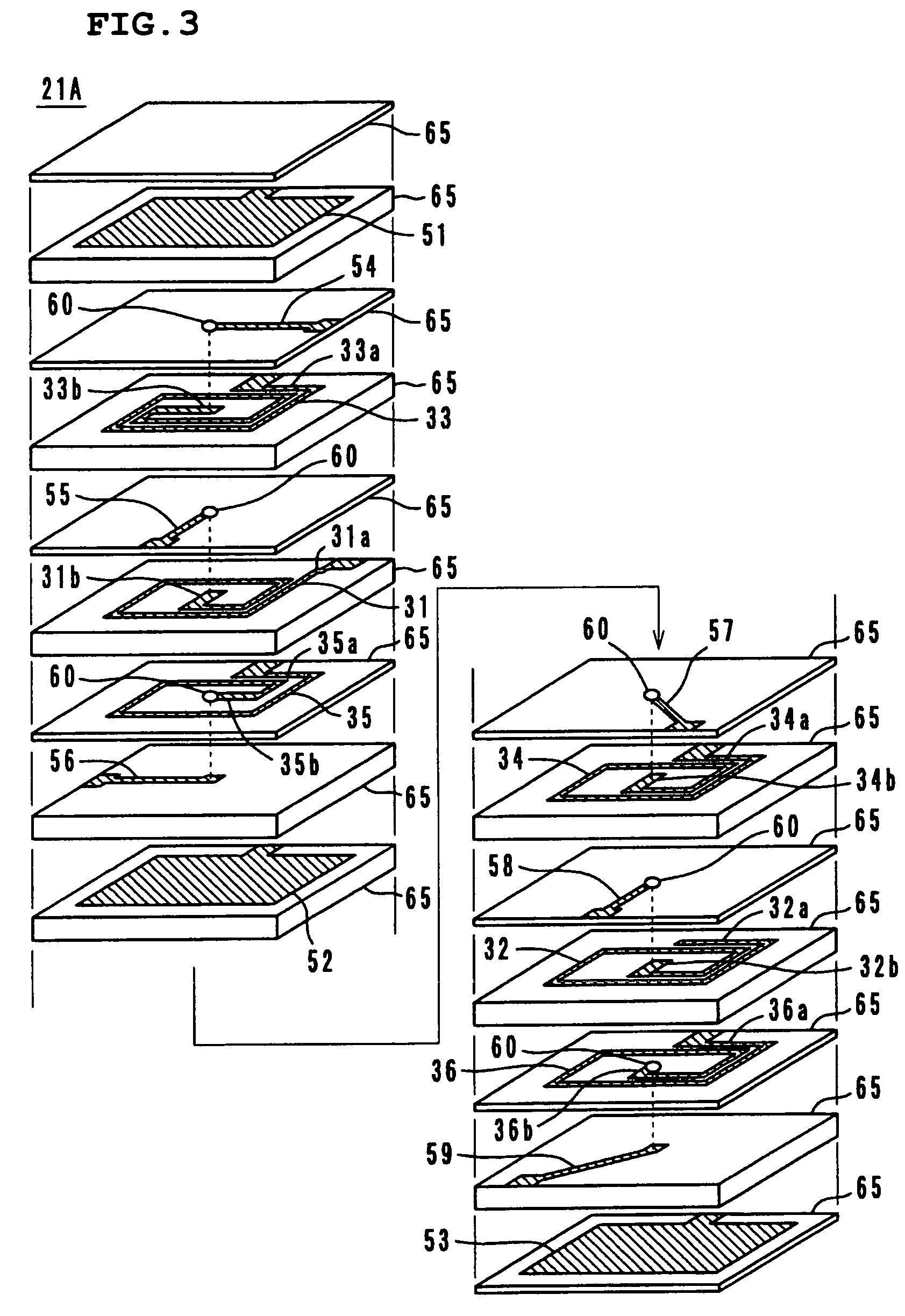
[0049]FIG. 3 is an exploded perspective view of a laminated balanced splitter 21A incorporating the balanced splitter 21 shown in FIG. 1. The balanced splitter 21A is composed of dielectric sheets 65 having ground electrodes 51, 52, 53 arranged on surfaces thereof; dielectric sheets65 in which ¼ strip lines 31, 32, 33, 34, 35, 36 and inter-layer connecting via holes 60 are provided; dielectric sheets 65 in which extraction electrodes 54, 55, 56, 57, 58, 59 and the inter-layer connecting via holes 60 are provided; and an outer dielectric sheet 65 with no electrode.

[0050]As the material used for the dielectric sheets 65, dielectric ceramic powder kneaded with a binder, or the like, and formed into a sheet-like configuration is used. The strip lines 31 to 36 and the extraction electrodes 54 to 59 are formed by sputtering, vapor-deposition, printing, or the like, and are each made of a material such as Ag, Ag—Pd, or Cu. The inter-layer connecting via holes 60 are p...


PUM

PropertyMeasurementUnit
¼ wavelengthaaaaaaaaaa
resistance valueaaaaaaaaaa
impedanceaaaaaaaaaa

Abstract

A balanced splitter has six ¼ strip lines. The first and third strip lines are electromagnetically coupled to each other to form a coupler. The second and fourth strip lines are electromagnetically coupled to each other to form a coupler. The first and fifth strip lines are electromagnetically coupled to each other to form a coupler. The second and sixth strip lines are electromagnetically coupled to each other to form a coupler. The first and second strip lines are connected in series to form an unbalanced line, the third and fourth strip lines form a first balanced line, and the fifth and sixth strip lines form a second balanced line. First and second resistors are electrically connected between a first balanced terminal and a second balanced terminal, and between another first balanced terminal and another second balanced terminal, respectively.

Description

BACKGROUND OF THE INVENTION[0001]1. Field of the Invention[0002]The present invention relates to a balanced splitter, in particular, a balanced splitter for use in mobile communication devices, or the like.[0003]2. Description of the Related Art[0004]With the trend toward higher signal frequency, an increasing number of communication devices use a balanced signal for the purpose of improved anti-noise characteristics, and the like. For this reason, there is a need for an unbalanced / balanced converter for converting an unbalanced signal into a balanced signal. Further, there is also a need for a splitter for splitting a signal into two signals depending on the intended applications. Accordingly, there is a growing need for a component combining the functions of both the converter and the splitter, that is, an “unbalanced output / balanced input splitter (balanced splitter)” for splitting a single unbalanced signal into two balanced signals.[0005]As shown in FIG. 13, an unbalanced outpu...

Claims


Application Information

Patent Timeline
Patent Type & Authority Patents(United States)
IPC IPC(8): H03H7/42H01F27/28H01P5/10H01P5/12
CPCH01P5/10H01P5/12H01P5/16
Inventor NOSAKA, KOJI
Owner MURATA MFG CO LTD
Why Eureka
Try Eureka