Congestion control for communication

Inactive Publication Date: 2008-12-23
NEC CORP
View PDF14 Cites 18 Cited by
  • Summary
  • Abstract
  • Description
  • Claims
  • Application Information

AI Technical Summary

Benefits of technology

[0074]A second congestion control system according to this invention prepares the optimum congestion control command in consideration of both of a transmission frame amount and a transfer frame amount and never occurs a drastic rate degradation. Accordingly, it is possible to achieve the second object of this invention.
[0075]A third congestion control system according to this invention certainly transfers congestion notification to all of nodes which might affect the congestion and can cancel the congestion impartially and quickly. Accordingly, it is possible to achieve the third object of this invention.
[0076]A fourth congestion control system according to this invention can decrease an amount of control frames by discontinuing transfer of the congestion notification where any effect is not expected in a node on the way using a ring characteristic. As a result, it is possible to achieve the fourth object of this invention.
[0077]A fift

Problems solved by technology

However, the first prior art is disadvantageous in that an amount of transmission frames is restricted or limited on a flow which is not related to congestion and utility efficiency of a link is degraded.
This is because only one transmission queue is prepared and granularity of control is rough.
Although the granularity of control is made fine, it is difficult to identify the flows which become restriction candidate in the congestion detection node because of a large processing load.
In addition, the first prior art is disadvantageous in that there is a case where the congestion notification is transferred to a node which is not related to congestion.
However, the second prior art is disadvantageous in that there is some possibility that the amount of the transmission frames in the node for the congestion control is restricted or limited so as to be too small more than necessary when

Method used


Image

  • Congestion control for communication
  • Congestion control for communication
  • Congestion control for communication

Examples


first embodiment

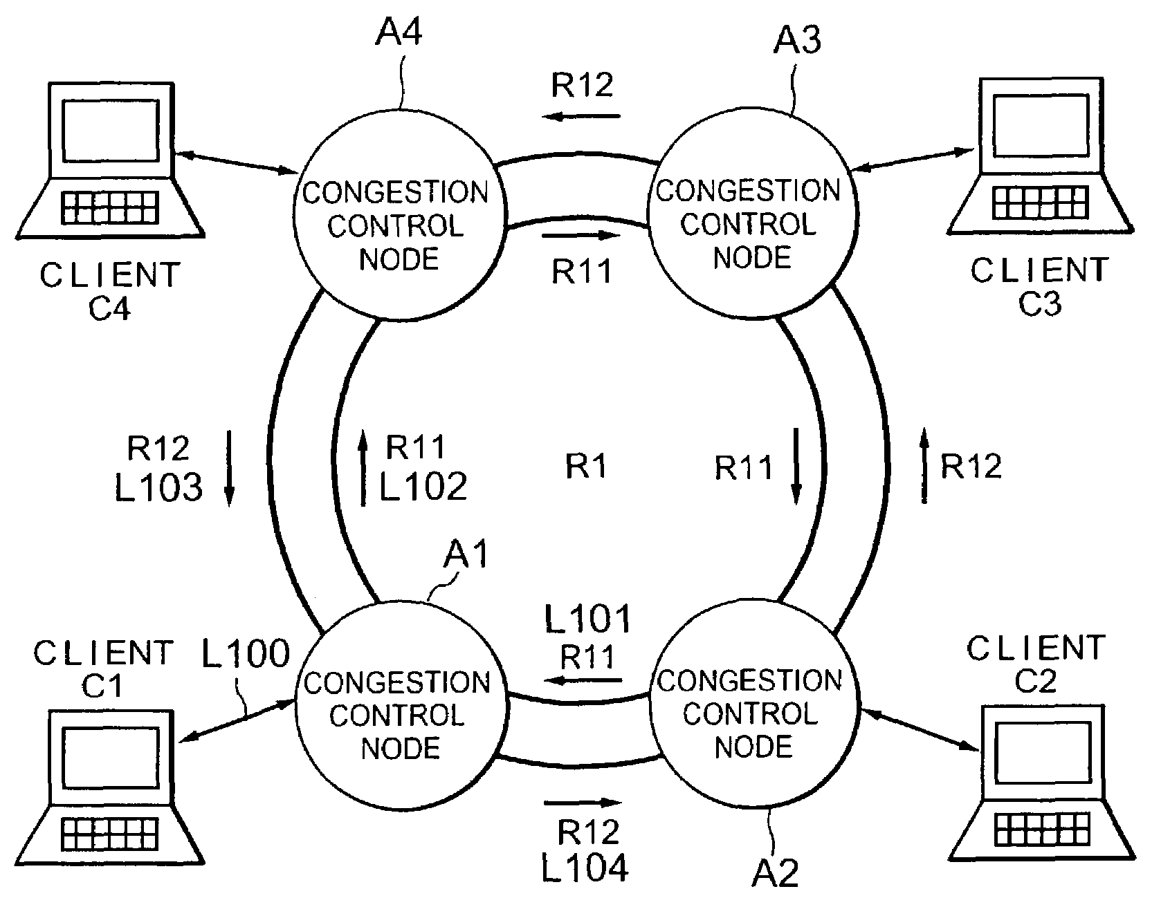
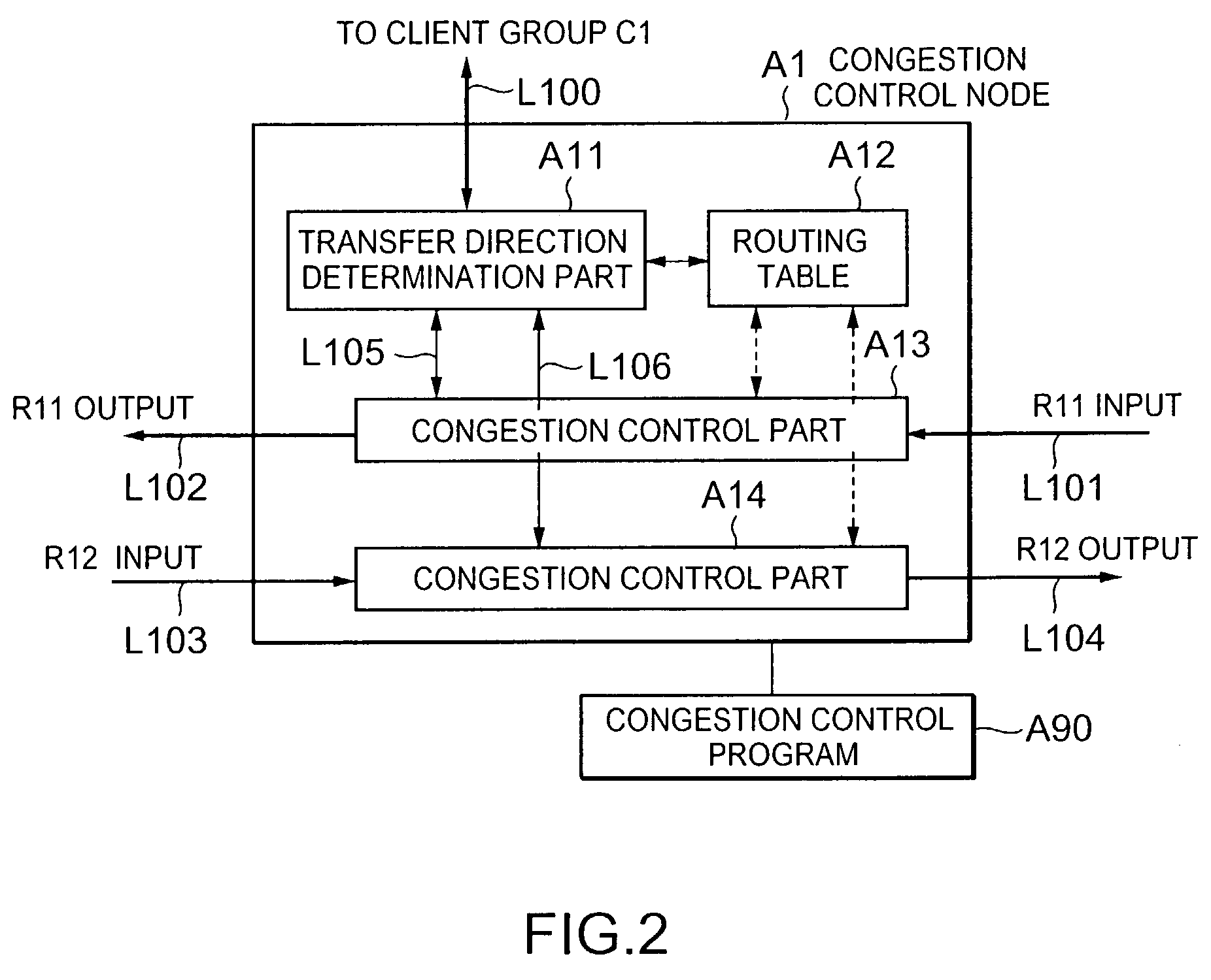
[0103]Referring to FIG. 1, the description will proceed to a congestion control system according to this invention. The illustrated congestion control system comprises a ring-shaped network R1, first and fourth client groups C1, C2, C3, and C4, and first through fourth congestion control nodes A1, A2, A3, and A4. The first through the fourth client groups C1 to C4 are connected to the first through the fourth congestion control nodes A1 to A4 through two-way links L100, respectively.

[0104]The ring-shaped network R1 comprises a first one-way ring R11 turning around or flowing in a clockwise direction and a second one-way ring R12 turning around or flowing in a counterclockwise direction in the opposite direction to the first one-way ring R11. The first and the second one-way rings R11 and R12 are collectively called the ring-shaped network R1. The ring-shaped network R1 has a function for transferring frames sent from one of the first through the fourth congestion control nodes A1 to...

second embodiment

[0318]Referring now to FIG. 9, the description will proceed according to this invention.

[0319]The second embodiment of this invention corresponds to a case where operation in the congestion notification reception transfer portion A134 on reception of congestion notification is changed in the first embodiment of this invention.

[0320]In the second embodiment of this invention, steps 201-211 in FIG. 9 carry out operations similar to the steps 201-211 in the first embodiment of this invention illustrated in FIG. 8.

[0321]Referring to FIG. 9, the second embodiment of this invention is different from the first embodiment of this invention illustrated in FIG. 8 at a point where the operation for transferring the received congestion notification frame to the adjustment node (step 3) is carried out after the operation for determining the queues for restriction candidates (steps 204-206).

[0322]With this structure, when it is determined that its own node has no relation to congestion in the ste...

fourth embodiment

[0388]Referring to FIG. 15, the description will be made as regards operation of the congestion notification transmission part B133 in a case a congestion control function is effective in the congestion notification transmission part B133 in this invention in detailed.

[0389]A difference point between FIG. 15 and FIG. 7 in the first embodiment of this invention is a point to make a control command (congestion control command) included in the congestion notification change according to conditions.

[0390]The congestion notification transmission part B133 periodically makes the buffer used amount measuring part A138 confirm the absence or absence of congestion occurrence in the transit buffer part B131 (step 301).

[0391]The step 301 is followed by a step 302 at which the congestion notification transmission part B133 receives a notification of the presence or absence of the congestion occurrence from the buffer used amount measuring part A138. When the congestion occurrence is present, th...


PUM


Abstract

In a congestion control system for congestion controlling communications on a network, a congestion control node has a congestion detection part for detecting a congestion level of the communications in the congestion control node in question and a congestion notifying part for notifying other congestion control nodes on the network of congestion information detected by the congestion detection part. The congestion control node further has a part for receiving the congestion information from the other congestion control nodes and a congestion flow estimating part for estimating, with reference to the congestion information and a routing table for designating a transfer path to destination, a flow having the congestion level that is not less than a predetermined level in the transfer path to the destination.

Description

BACKGROUND OF THE INVENTION[0001]This invention relates to a congestion control for communications and, more particularly, to a congestion control system, a congestion control node, and a congestion control program for controlling congestion of communications in a ring-shaped network.[0002]In prior art, a congestion control system of the type described carries out a congestion control in a network having ring-shaped topology and is used to avoid congestion of a ring band.[0003]Various congestion control systems of the type are already known. By way of example, a congestion control system is described by D. Tsiang & G. Suwala in a standardized document published from IETF, Request for Comments: 2892, Cisco Systems, August 2000, pages 9 and 28-32 under the title of “The Cisco SRP MAC Layer Protocol.” In the congestion control system described in this standardized document, each congestion control node comprises a single transmission queue. When a congestion is detected in a transfer / t...

Claims


Application Information

Patent Timeline
IPC IPC(8): H04L1/00H04L12/26H04L12/28H04L12/56H04L12/42H04Q11/04
CPCH04L47/10H04L47/11H04L47/12H04L47/30H04Q11/0478H04L2012/5636H04L2012/5678
Inventor ENOMOTO, NOBUYUKIIWATA, ATSUSHI
Owner NEC CORP
Why Eureka
Try Eureka