Method and apparatus for calculating voltage drop

a technology of voltage drop and voltage drop, applied in the field of fire alarm systems, can solve the problems of increased line loss, inability to accurately calculate actual voltage drop of appliances, and inability to operate properly of devices,

Inactive Publication Date: 2008-12-23
JOHNSON CONTROLS FIRE PROTECTION LP
View PDF9 Cites 10 Cited by
  • Summary
  • Abstract
  • Description
  • Claims
  • Application Information

AI Technical Summary

Problems solved by technology

If the voltage is below the operating range, the appliance may not operate properly, producing visible signal intensities or sound pressure levels below the levels of the designed system.
The increase in current draw at lower voltages also results in greater line loss than when operating under normal conditions.
Calculating actual voltage drop for appliances is extremely difficult, especially for T-Tapped circuits.
This method often results in severely limiting wiring distance, which is undesirable.

Method used


Image

  • Method and apparatus for calculating voltage drop
  • Method and apparatus for calculating voltage drop
  • Method and apparatus for calculating voltage drop

Examples


Embodiment Construction

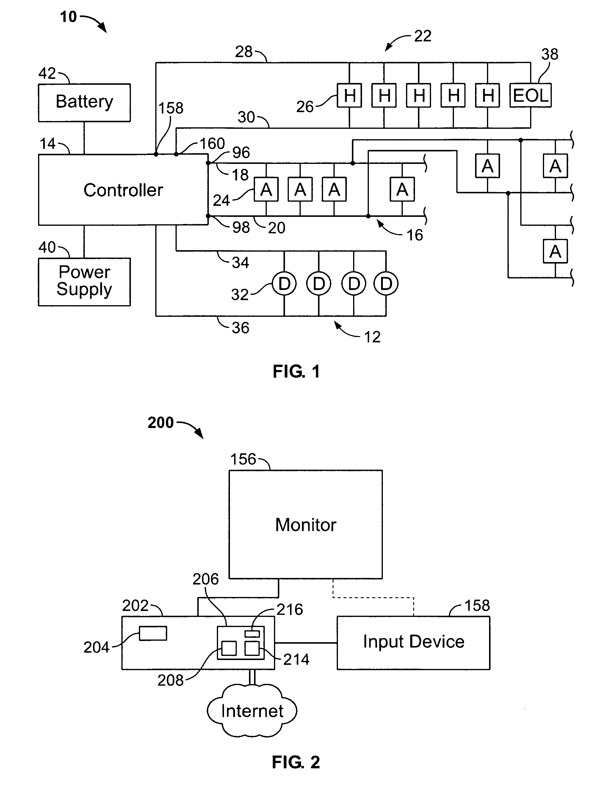
[0026]FIG. 1 illustrates an alarm system 10 formed in accordance with an embodiment of the present invention. The system 10 includes one or more detector networks 12 having individual alarm condition detectors 32 which are monitored and controlled by a controller 14 or control panel. The detectors 32 may detect fire, smoke, temperature, chemical compositions, or other conditions. The alarm condition detectors 32 are coupled across a pair of power lines 34 and 36. When an alarm condition is sensed, the controller 14 signals the alarm to the appropriate notification devices through one or more networks 16 of addressable notification appliances 24 and / or one or more networks 22 of hardwired (e.g. non-addressable) notification appliances 26. The networks 16 and 22 are also referred to as notification appliance circuits (NAC).

[0027]Wiring is used to form the networks 16 and 22. The length of wire, wire size and notification appliance load all vary according to specific requirements for e...


PUM


Abstract

A method for performing voltage drop calculations in an alarm circuit comprises creating a circuit to be controlled. A first device is selected from a list of devices to add to the circuit. An estimated power supply of the first device is calculated using modified nodal analysis of the circuit and it is determined whether the estimated power supply of the first device is sufficient power for the first device to operate.

Description

BACKGROUND OF THE INVENTION[0001]This invention relates generally to fire alarm systems, and more particularly, to methods and apparatus for calculating power conditions at devices prior to installation.[0002]In general, alarm systems include several notification appliances that are joined to common power lines extending from a control panel. Notification appliances may be wired as notification circuits by routing the wiring from the control panel to each device in succession. Alternatively, when wired as signaling lines, the wires may spoke off to form multiple wiring runs or branches. Forming branches in signaling line circuits is also referred to as “T-Tapping”.[0003]Notification appliances have one or more alarm indicators (e.g., strobes and horns) to notify people in the area of an alarm condition. Each notification appliance has a power operating range within which the device operates. A predefined or predetermined power (e.g., voltage and current) operating range may be set b...

Claims


Application Information

Patent Timeline
Patent Type & Authority Patents(United States)
IPC IPC(8): G06F17/50
CPCG01R31/2827
Inventor BROOKS, JEFFAKBUDAK, HALUKBARRIEAU, MARKSAVAGE, KENNETH
Owner JOHNSON CONTROLS FIRE PROTECTION LP
Why Eureka
Try Eureka