
Asymmetrical bus

a bus and asymmetric technology, applied in the field of high-speed buses, can solve the problems of high asymmetric bus variable traffic between two components, and difficult to optimize power consumption and performance simultaneously

Inactive Publication Date: 2008-12-23
NVIDIA CORP
View PDF2 Cites 58 Cited by
  • Summary
  • Abstract
  • Description
  • Claims
  • Application Information

AI Technical Summary

Benefits of technology

[0011]In one embodiment the bus interface includes a set of receivers and transmitters. A link control module forms a bidirectional link with the other bus interface by configuring the receivers as part of a unidirectional sub-link in a downstream direction and configuring the transmitters as part of a unidirectional sub-link in an upstream direction. An asymmetry controller regulates the upstream bandwidth and the downstream bandwidth in response to a control signal.

Problems solved by technology

One problem associated with conventional PCIe is that traffic between two components is variable.
Since a PCIe bus consumes a significant amount of power which increases with the number of active data lanes, the bus size is often a compromise between power and performance.
However, the bus traffic between two components may also be highly asymmetric during certain time intervals.
Large asymmetries in bus traffic make it difficult to simultaneously optimize power consumption and performance.

Method used


Image

  • Asymmetrical bus
  • Asymmetrical bus
  • Asymmetrical bus

Examples


Embodiment Construction

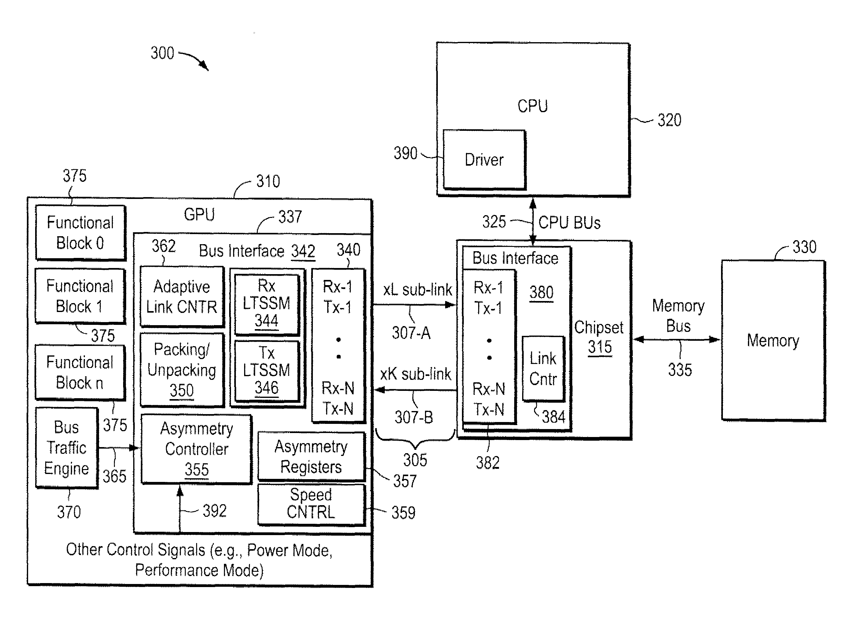
[0022]FIG. 3 illustrates a system 300 that includes a bus 305 between two integrated circuit components, such as a graphics processing unit (GPU) 310 and a chipset 315. System 300 may also include a CPU 320 coupled to chipset 315 by a CPU bus 325. A system memory 330 may be coupled to chipset 315 ay a memory bus 335.

[0023]Bus 305 includes two unidirectional sub-links 307-A and 307-B. That is, bus 305 establishes a bidirectional link that has a one-way link 307-A in a first direction and a one-way link 307-B in another direction. Unidirectional sub-link 307-A is used by GPU 310 to transmit information to chipset 315. Unidirectional sub-link 307-B is used by GPU 310 to receive information from chipset 315. In accordance with one convention, traffic headed away from bus interface 337 of GPU 310 to chipset 315 is directed “upstream” whereas traffic headed from chipset 315 towards bus interface 337 of GPU 310 is directed “downstream.” Unidirectional sub-link 307-A is thus a one-way “upst...


PUM


Abstract

A bus interface permits an upstream bandwidth and a downstream bandwidth to be separately selected. In one implementation a link control module forms a bidirectional link with another bus interface by separately configuring link widths of an upstream unidirectional sub-link and a downstream unidirectional sub-link.

Description

CROSS REFERENCE TO RELATED APPLICATIONS[0001]This application is a continuation-in-part of U.S. patent Ser. No. 11 / 229,208 by William Tsu et al., filed on Sep. 16, 2005, which is a continuation-in-part of U.S. patent Ser. No. 10 / 431,994, filed on May 7, 2003 now U.S. Pat. No. 7,136,953.FIELD OF THE INVENTION[0002]The present invention is generally related towards high-speed buses having a plurality of data lanes. More particularly, the present invention is directed towards systems in which a high-speed bus having a plurality of data lanes may experience large differences in upstream and downstream traffic.BACKGROUND OF THE INVENTION[0003]FIG. 1 illustrates two components 105 and 110 which communicate via a Peripheral Component Interface Express (PCIe) bus 115. Each component 105 and 110 includes a bus interface 120. Bus interface 120 includes a physical layer 125, such as drivers, transmitters, receivers, input buffers and other circuits to support the PCIe bus 115. PCIe is a packet...

Claims


Application Information

Patent Timeline
Patent Type & Authority Patents(United States)
IPC IPC(8): G06F13/40
CPCG06F13/4018Y02B60/1235Y02B60/1228Y02D10/00
Inventor TSU, WILLIAM P.CASE, COLYN S.
Owner NVIDIA CORP
Features
  • Generate Ideas
  • Intellectual Property
  • Life Sciences
  • Materials
  • Tech Scout
  • Unparalleled Data Quality
  • Higher Quality Content
  • 60% Fewer Hallucinations
Learn More