Mounting structure for LED lighting systems

a technology for led lighting and mounting structures, applied in the field of lighting systems, can solve the problems of easy to turn out to be rather complex, present-day led lighting systems exhibit only limited integration possibilities, etc., and achieve the effects of facilitating maintenance and replacement of any single component, facilitating handling, connecting and mounting of the system, and improving the mounting structur

Active Publication Date: 2008-12-30
PATENT TREUHAND GESELLSCHAFT FUR ELECTRIC GLUEHLAMPEN MBH +1
View PDF17 Cites 49 Cited by
  • Summary
  • Abstract
  • Description
  • Claims
  • Application Information

AI Technical Summary

Benefits of technology

[0004]In view of the foregoing, the need is felt for improved mounting structures for LED lighting systems that i.a. i) may permit an extensive integration of the components of an LED lighting system, ii) result in lighting systems of compact size, iii) facilitate handling, connecting and mounting of the system, and iv) facilitate maintenance and replacement of any single component.

Problems solved by technology

These components require interconnections that may easily turn out to be rather complex.
In view of this, present day LED lighting systems exhibit only limited possibilities of integration.

Method used


Image

  • Mounting structure for LED lighting systems
  • Mounting structure for LED lighting systems
  • Mounting structure for LED lighting systems

Examples


Embodiment Construction

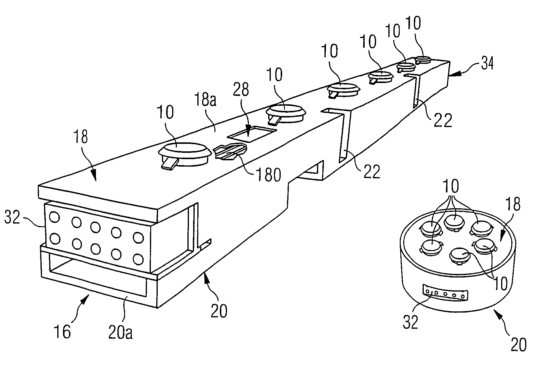
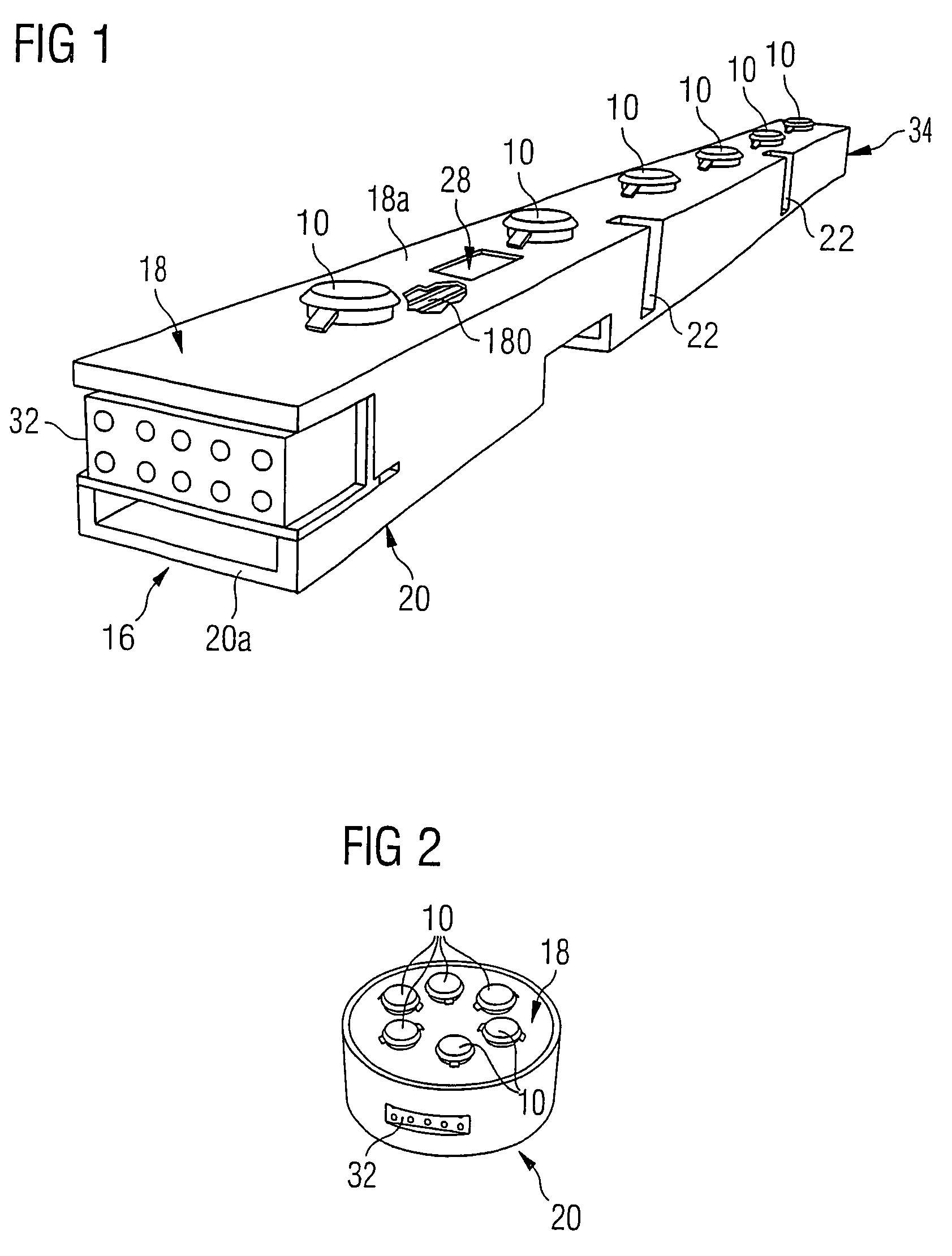
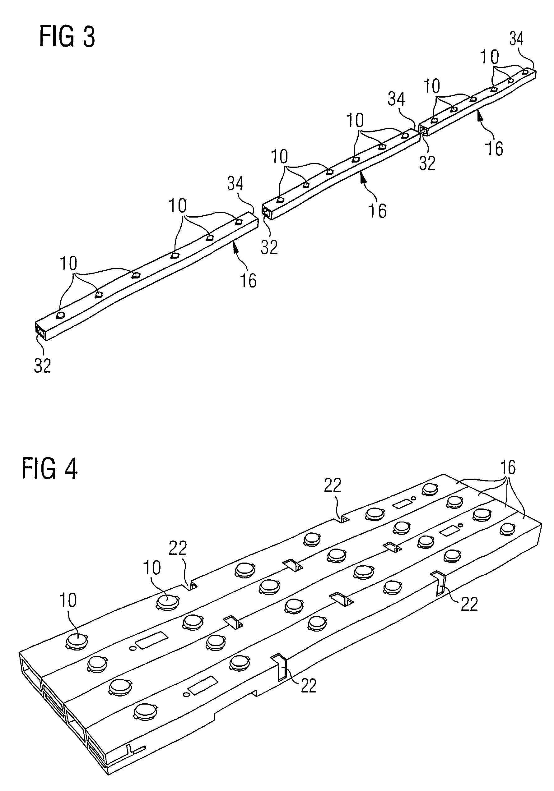
[0014]FIG. 1 is generally representative of a mounting structure for an LED lighting system including one or more LED lighting sources 10.

[0015]As illustrated herein, each of the light sources 10 includes an LED element that may be in association with a disc-like optical system to create a sort of button-like assembly. Nevertheless, any other (possibly bigger) optical system may used within the framework of the arrangement described herein, the same also applying to light sources with a fixed optical system or without any optical system at all. Such an assembly is known in the art and resorting to such an assembly is not a mandatory requirement of the invention: in fact the invention as disclosed herein is applicable to LED lighting sources having different shapes and / or included in different type of assemblies, including assemblies that do not comprise an associated optical system.

[0016]All the light sources 10 are attached to a circuit board 18a with conductive traces 180 to feed ...


PUM


Abstract

A mounting structure for LED lighting sources, includes a support body having attached on one side thereof a circuit board for mounting the LED lighting sources. The circuit board is preferably a printed-circuit board with conductive traces to feed electrical power to the LED lighting sources. The support body is in the form of an elongated bar or a box with a linear, round, square, hexagonal or octagonal shape. The support body is a drawn or molded body of a lightweight material and preferably exhibits good heat transfer properties. The support body includes a back side for mounting the structure on a supporting surface, such back side possibly having associated a heat dissipation fixture. Additionally, the support body may have free space inside and / or be at least partially apertured to permit cooling air flow for a driver circuit for driving the LED lighting source.

Description

FIELD OF THE INVENTION[0001]The present invention relates to lighting systems including light emitting diodes (LEDs) as light sources.DESCRIPTION OF THE RELATED ART[0002]In addition to their established use as display elements, light emitting diodes (LEDs) are becoming increasingly popular as lighting sources. This applies primarily to so-called high-flux or high-brightness LEDs.[0003]An LED lighting system typically includes a number of components such as one or more LED light sources, a driver circuit, a heat sink, optics, connection means, ancillary mounting elements. These components require interconnections that may easily turn out to be rather complex. In view of this, present day LED lighting systems exhibit only limited possibilities of integration. For example, the driving circuits are usually implemented as a part of the power supply module.OBJECT AND SUMMARY OF THE INVENTION[0004]In view of the foregoing, the need is felt for improved mounting structures for LED lighting ...

Claims


Application Information

Patent Timeline
Patent Type & Authority Patents(United States)
IPC IPC(8): H01R33/00F21S4/00H01L33/00H01L33/48
CPCF21S2/005F21S4/008F21V21/005F21V23/06F21Y2101/02F21S4/28F21Y2115/10
Inventor HACKER, CHRISTIANMASCHIETTO, ALESSANDROSCILLA, GIOVANISCORDINO, ALESSANDRO
Owner PATENT TREUHAND GESELLSCHAFT FUR ELECTRIC GLUEHLAMPEN MBH
Why Eureka
Try Eureka