Method and apparatus for optimizing transmitter power efficiency

a technology of transmission power and optimization method, applied in the field of communication system transmission power efficiency optimization, can solve the problems of extending battery life, complicating the problem, and using modulation schemes, and achieve the effect of optimizing transmitter power efficiency

Active Publication Date: 2008-12-30
MALIKIE INNOVATIONS LTD
View PDF16 Cites 26 Cited by
  • Summary
  • Abstract
  • Description
  • Claims
  • Application Information

AI Technical Summary

Problems solved by technology

One of the main difficulties in extending battery life is related to the modulation schemes now being used.
Further complicating the problem is the stochastic nature of the required transmitter power.

Method used


Image

  • Method and apparatus for optimizing transmitter power efficiency
  • Method and apparatus for optimizing transmitter power efficiency
  • Method and apparatus for optimizing transmitter power efficiency

Examples


Embodiment Construction

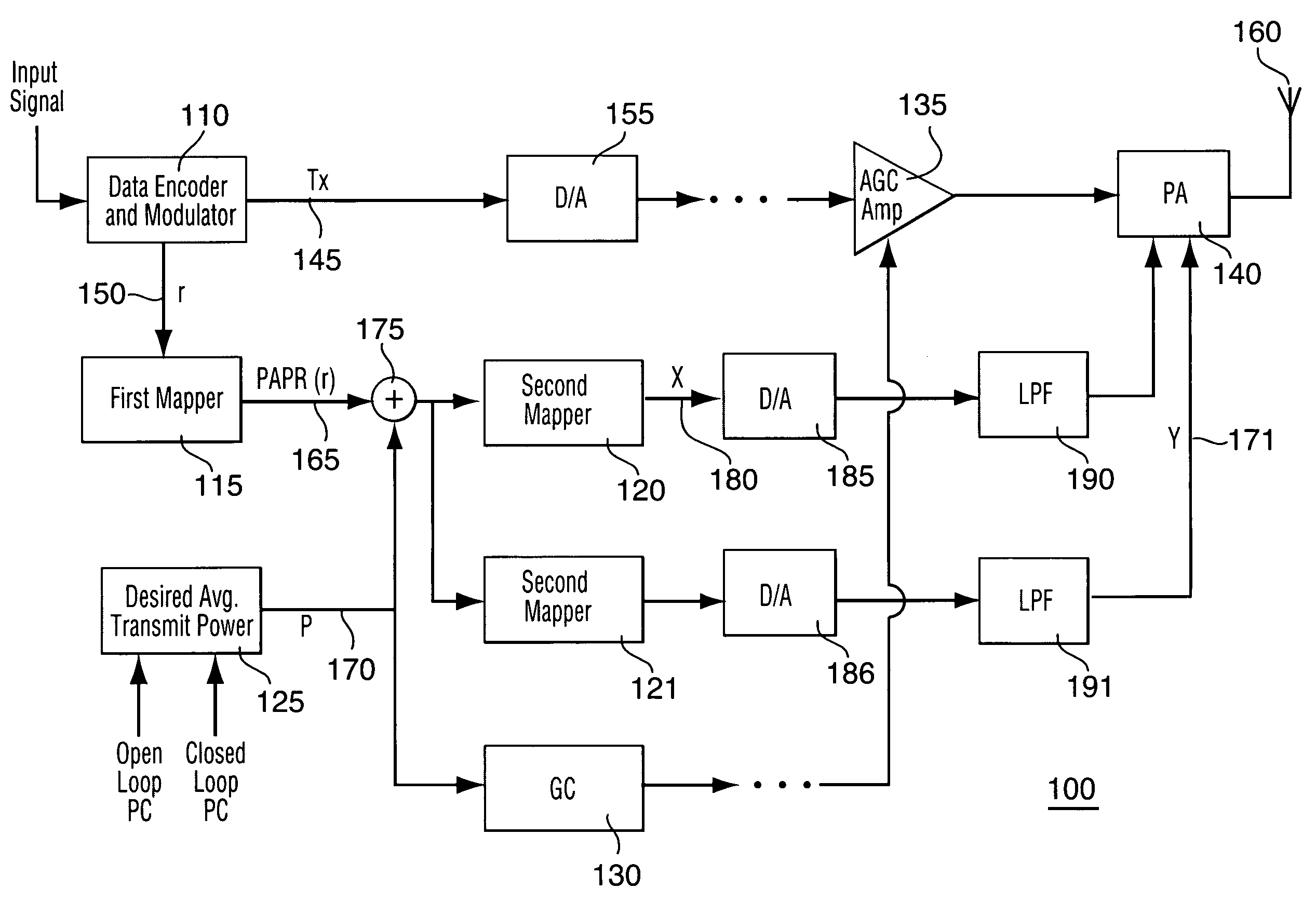
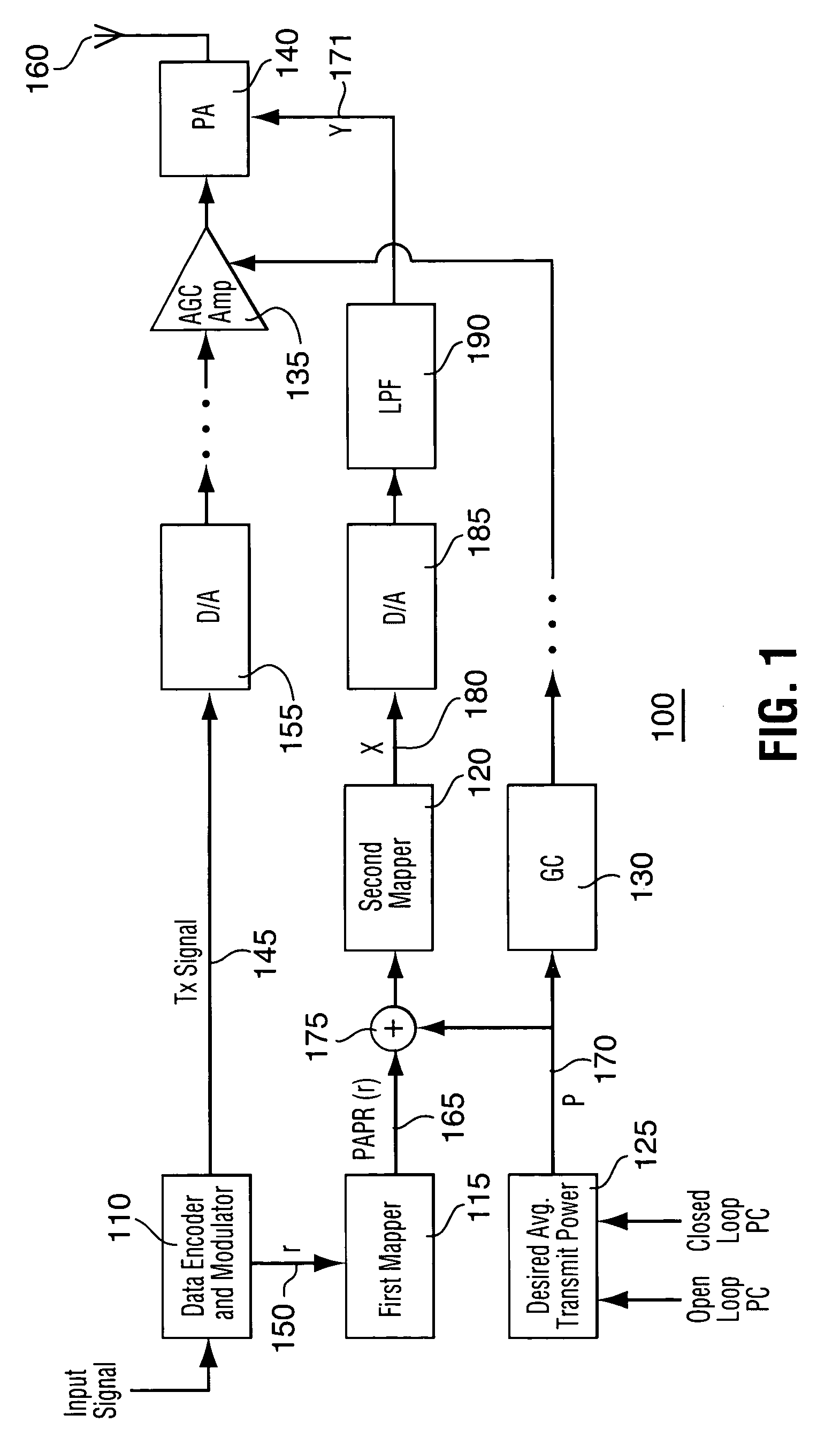
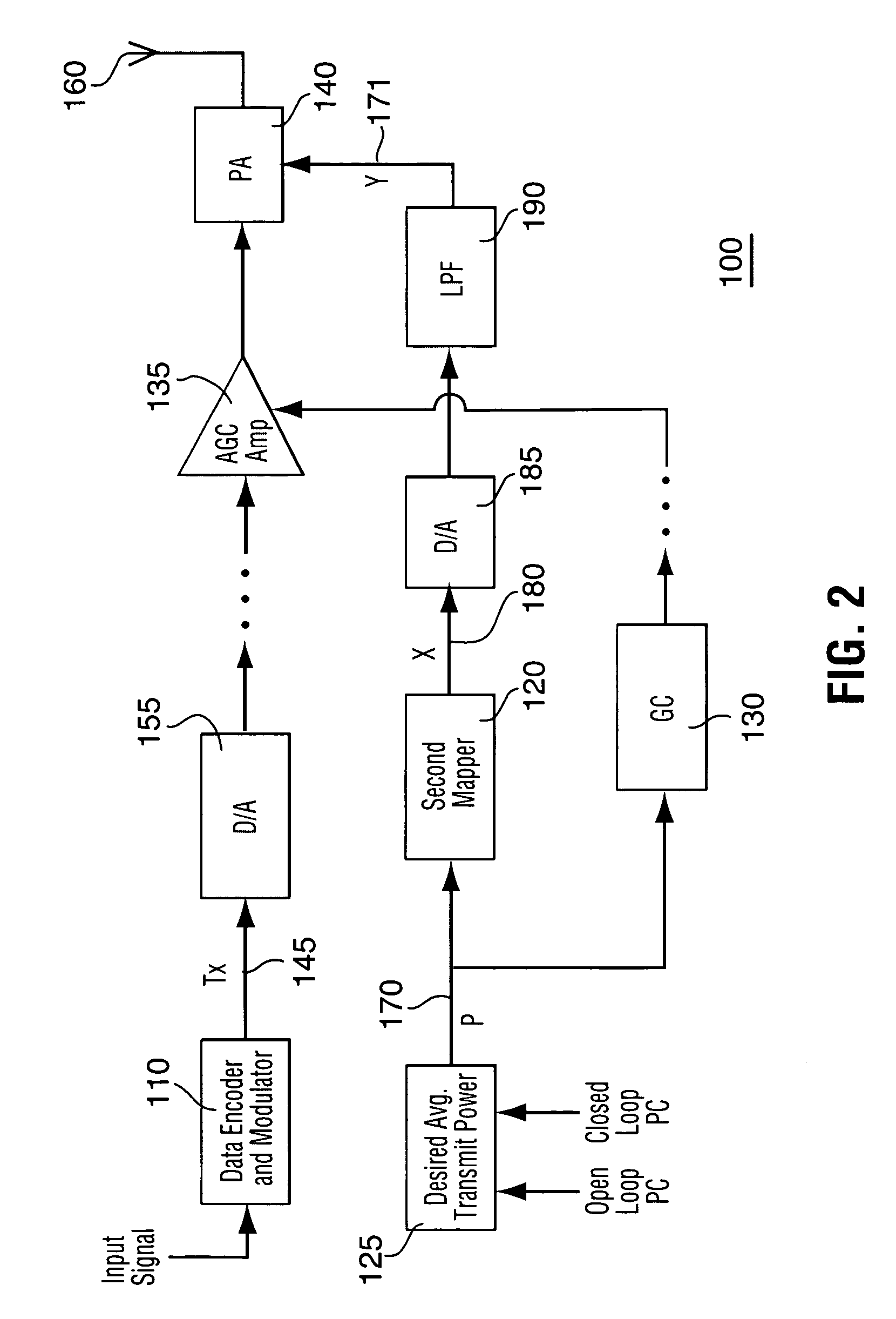
[0022]The embodiments of the transmitter power optimization of the present invention provide a way to improve power efficiency of transmitters having varying transmit power and high PAPR. The transmitter circuits control various circuit parameters that are adjusted continuously to optimize power efficiency. These parameters can include, but are not limit to, dynamic range, gain, bias, conduction angle, power supply voltage, a stage switch-in feature, a stage switch-out feature, number of amplifying stages, a turning on feature, a turning off feature, a charging duty cycle, an amplifier class change feature, a load, or an impedance.

[0023]Reference is now made to the drawings. FIG. 1 illustrates a simplified block diagram of a transmitter apparatus 100 in accordance with the present invention. The transmitter 100 comprises a data encoder and modulator 110. The data encoder and modulator 110 converts a digital signal to be transmitted to the modulation technique appropriate to the air ...


PUM


Abstract

A peak to average power ratio signal is generated from a first mapping function that selects the peak to average power ratio signal that corresponds to the data rate or data format of the signal to be transmitted. The selected peak to average power ratio signal is summed with a desired average transmit power signal. The resulting summation signal is input to a second effectively continuously valued mapping function comprising a table that has a plurality of power amplifier control signal values each with a corresponding peak transmit power. Each peak transmit power signal value results in a power amplifier control signal value that achieves the best possible transmitter power efficiency while still meeting out of band spurious emissions and waveform quality requirements. The summation signal value maps to one of the power amplifier control signal value that is then used to adjust a parameter such as bias of the power amplifier.

Description

RELATED APPLICATIONS[0001]The present application claims priority from U.S. provisional application Ser. No. 60 / 430,293 filed on Dec. 2, 2002, the complete drawings and specification of which are incorporated herein by reference.FIELD OF TECHNOLOGY[0002]The present invention relates to transmitter power efficiency in communication systems and in particular to optimizing transmitter power efficiency in communication systems.BACKGROUND TO THE INVENTION[0003]Mobile electronic devices, such as radios and cellular telephones, typically rely on power from one or more internal batteries. A major performance criterion for such devices is the battery life, which is typically defined as the time period for which the battery will power the device on a single charge. A large portion of the battery power is consumed in a power amplifier (PA) section of the mobile electronic device's transmitter. The power amplifier section amplifies the power of a signal to be transmitted from a comparatively lo...

Claims


Application Information

Patent Timeline
Patent Type & Authority Patents(United States)
IPC IPC(8): H04L25/03H03G3/30H04B7/005H04L27/26
CPCH03G3/3042H04W52/52H04L27/2614Y02B60/50
Inventor CHAN, WEN-YENJIN, XINJIAO, QING ZHONG
Owner MALIKIE INNOVATIONS LTD
Why Eureka
Try Eureka