Cutter grinding device

a grinding device and cutter technology, applied in the field of cutter grinding devices, can solve the problems of difficult and time-consuming, easy damage to cutters, and easy damage to cutters, and achieve the effect of convenient and convenient us

Inactive Publication Date: 2009-01-06
LEE WANG SHENG
View PDF9 Cites 17 Cited by
  • Summary
  • Abstract
  • Description
  • Claims
  • Application Information

AI Technical Summary

Benefits of technology

[0006]The main objective of the invention is to provide a cutter grinding de...

Problems solved by technology

However, using grinding wheels to sharpen cutters requires an experienced technician with great skill, otherwise the cutter is ...

Method used


Image

  • Cutter grinding device
  • Cutter grinding device
  • Cutter grinding device

Examples


first embodiment

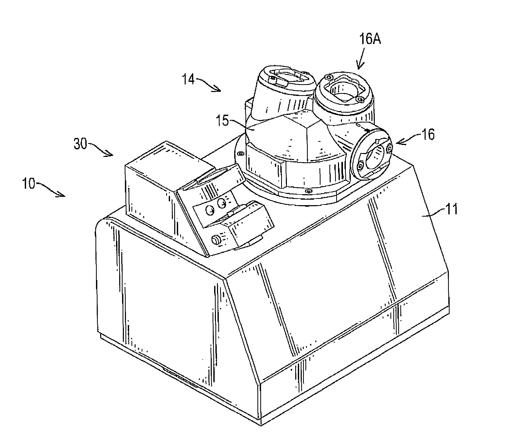
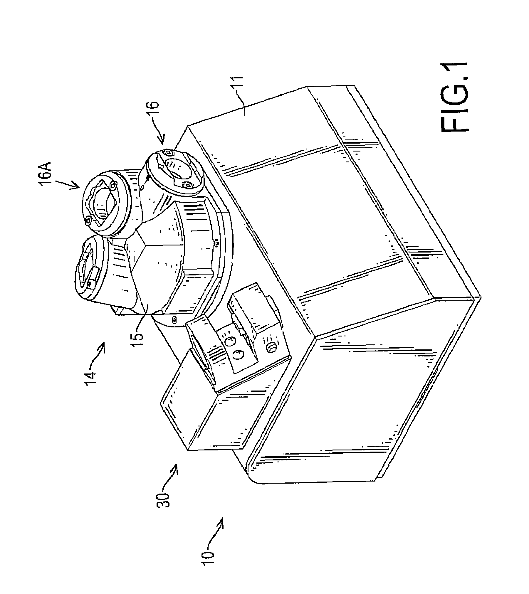
[0036]In a first embodiment the bracket (16) comprises one pair of holding blocks (164) and is preferably mounted over the front hole (151).

[0037]In a second embodiment the bracket (16A) comprises two pairs of holding blocks (164) formed perpendicular to each other and the height of the holding blocks is less than the first embodiment and is mounted over the disc-edge and disc-top holes (152, 153).

[0038]With further reference to FIGS. 3, 8 and 9, the clamping assembly (20) is selectively mounted into one of the brackets (16, 16A), holds a milling cutter (A) and comprises an outer sleeve (21), a core (23), a clamping base (22) and a bearing.

[0039]The outer sleeve (21, 21A) comprises an inserting end, a clamping end (212), an inserting tube (211), a shoulder (213, 213A) and multiple holding surfaces (2131, 2131A, 2131B, 2132, 2132A, 2132B).

[0040]The clamping end (212) has an inner thread formed therein.

[0041]The inserting tube (211) is formed on the inserting end, is selectively inser...

second embodiment

[0044]In second embodiment of the outer sleeve (21A), as shown in FIGS. 10 and 11, the outer sleeve comprises nine holding surfaces (2131A, 2131B, 2132A, 2132B) defined around the annular edge of the shoulder (213A) and comprises four rhombic deep holding surfaces (2131A), two parallel shallow holding surfaces (2132A) and three triangular holding surfaces (2131B, 2132B), wherein one triangular holding surface is a deep triangular holding surface (2131B) and two triangular holding surfaces are shallow triangular holding surfaces (2132B).

[0045]The four rhombic deep holding surfaces (2131A) comprise two pairs of parallel deep surfaces that intersect at an apex on a diameter of the shoulder (213A). The apex has an included angle of 120°.

[0046]The two parallel shallow holding surfaces (2132A) intersect the parallel deep surfaces at an inflexion having an included angle of 120°, thereby forming a regular hexagon.

[0047]The triangular holding surfaces (2131B, 2132B) form an equilateral tria...


PUM

PropertyMeasurementUnit
Angleaaaaaaaaaa
Diameteraaaaaaaaaa
Heightaaaaaaaaaa

Abstract

A cutter grinding device has a housing, a motor, a grinding wheel, a holding cap, multiple cutter holding brackets and a cutter clamping assembly. The holding cap is mounted on the housing, encloses the grinding wheel and has multiple holes formed on corresponding axis coinciding with different portions of the grinding wheel. The brackets are mounted respectively in the inserting holes in the holding cap and each has a working hole aligning with the corresponding hole in the holding cap and at least one pair of holding blocks. The holding blocks on the holding brackets have different heights to hold fins of a milling cutter at different positions and angles when inserted into the brackets. Accordingly, the milling cutter can be ground at different angles with the cutter grinding device conveniently and easily.

Description

BACKGROUND OF THE INVENTION[0001]1. Field of the Invention[0002]The present invention relates to a cutter grinding device, and more particularly to a grinding device for a milling cutter.[0003]2. Description of Related Art[0004]To sharpen a cutter, such as a milling cutter, a grinding machine with grinding wheels is always used. However, using grinding wheels to sharpen cutters requires an experienced technician with great skill, otherwise the cutter is easily damaged or blunted. Therefore, to sharpen a cutter with a conventional grinding machine is costly, difficult and time-consuming.[0005]To overcome the shortcomings, the present invention tends to provide a cutter grinding device to mitigate or obviate the aforementioned problems.SUMMARY OF THE INVENTION[0006]The main objective of the invention is to provide a cutter grinding device that is easy and convenient to use for grinding a cutter at different angles.[0007]The cutter grinding device comprises a housing, a motor, a grindi...

Claims


Application Information

Patent Timeline
IPC IPC(8): B24B7/00B24B19/00B24B9/00B24B55/04
CPCB24B3/02
Inventor LEE, WANG-SHENG
Owner LEE WANG SHENG
Why Eureka
Try Eureka