Particulate matter reducing apparatus

a technology of reducing apparatus and particulate matter, which is applied in the direction of machines/engines, combustion-air/fuel-air treatment, chemical/physical processes, etc., can solve the problems of clogging intensively and biasedly, affecting the health of human body and environment, and affecting so as to minimize the trouble of cleaning and the effect of reducing the frequency of filter cleaning

Inactive Publication Date: 2009-01-06
CLEAN DIESEL TECHNOLOGIES
View PDF25 Cites 40 Cited by
  • Summary
  • Abstract
  • Description
  • Claims
  • Application Information

AI Technical Summary

Benefits of technology

[0059](5) The particulate matter reducing apparatus of the present invention has operational advantages as described below (refer to the first to fifth points). First, (a) the filter is set to have a low collection rate, and (b) the filter is regenerated after the particulate matter is burned and eliminated while being collected on the filter. Further, continuous burning of the particulate matter is possible by the wire of which the main component is Fe, which functions as an oxidation catalyst, an oxidation catalyst with which the wire is coated, or a fuel borne catalyst and the like. Thus, continuous regeneration of the filter is possible.
[0060](c) The exhaust gas is dispersed and the particulate matter is evenly collected on the filter because the intake and exhaust surfaces of the filter are formed along the flow of the gas in a large area.
[0061]With these (a), (b), and (c), the filter barely reaches a permissible amount and a collection limit. As a result, clogging barely occurs and the frequency of filter cleaning becomes low.
[0062](6) Second, (a) this filter is provided so that the filling density of the wire is 40% or less and a low collection rate is attained. The diameter of the central through hole is almost the same as, or larger than, that of the exhaust pipe and it is also considered to increase the number of superpositions (laminations). (b) Since elimination of the particulate matter is possible by continuous burning thereof, regeneration of the filter is possible. (c) The exhaust gas is dispersed so that the particulate matter is evenly collected.
[0063]With these (a), (b), and (c), resistance to the flow of the exhaust gas and pressure loss are also small. As a result, the increase of back pressure on the upstream side is avoided and a bad influence on the diesel engine is also avoided.
[0064](7) Third, the filter is composed of (a) a wire mesh structure of which the diameter of the wire is 0.2 mm or more and is provided to attain a low collection rate. (b) Continuous burning of the particulate matter is possible. (c) The exhaust gas is dispersed to evenly collect the particulate matter.
[0065]With these (a), (b), and (c), burning the particulate matter in large quantity at one time to abruptly increase the temperature is avoided. However, continuous and early burning of the particulate matter in small quantity is possible. In this manner, the temperature rise of the filter can be controlled to prevent melting and damage of the filter by heat.
[0066](8) Fourth, this reducing apparatus is composed of a simple structure whereby the filter is retained within the outer cylindrical casing by a pair of shielding plates. Thus, cleaning and the like can be readily carried out.
[0067](9) Fifth, in this reducing apparatus, the filter of a low collection rate is used, but it is also possible to obtain a high reduction and purification rate using the oxidation catalyst and the fuel borne catalyst together.
[0068]The particulate matter reducing apparatus according to the present invention is characterized in that one or more filters are adopted in combination with each of the following:
[0069]That is, a wire mesh structure; a short column shape with one central Through-hole; a coaxial arrangement within an outer cylindrical casing; a pair of shielding plates with one or more air holes; the diameter and filling density of a wire; a low collection rate; a wire of which the main component is Fe; an oxidation catalyst; a fuel borne catalyst, etc.
[0071]First, the filter is barely clogged and it is possible to minimize the trouble of cleaning. Namely, the filter of the present invention is not a method of a high collection rate as seen in the conventional example of the kind described above, but a method of a low collection rate, wherein the filter is regenerated by burning the particulate matter while collecting. The collected particulate matter can be continuously burned and thus, the filter can also be continuously regenerated.
[0072]In particular, the wire of which the main component is Fe, the oxidation catalyst with which the wire is coated, and the fuel borne catalyst are effective for this. Further, since it is evenly collected, the particulate matter is not intensively and biasedly collected differently from the conventional example of the kind described above.
[0073]With these, the filter barely reaches its permissible amount and collection limit compared with the conventional example of this kind described above and clogging barely occurs. For example, the frequency of filter cleaning can be decreased because it suffices if the cleaning is carried out about once a week. For the purpose of regenerating the filter, it is not necessary to adopt an electric heater, a heating furnace, an alternately regenerating method or the like. Thus, the filter is also excellent in terms of the cost of equipment and the running cost.
[0074]Second, the increase of back pressure is controlled to avoid an adverse influence on the diesel engine. Namely, in the filter of the present invention, the filling density of the wire is 40% or lower and a method of a low collection rate is adopted. The diameter of the central through hole is almost the same as or larger than that of the exhaust pipe. It is also possible to increase the number of superpositions (laminations). Further, the particulate matter is burned while being collected. In addition, elimination of the particulate matter is possible by continuously burning it, thereby making it possible to continuously regenerate the filter. Still further, the particulate matter is evenly collected.
[0075]With these, resistance to the exhaust gas and the pressure loss are small to avoid the increase of back pressure on the upstream side. Accordingly, excessive load is not imposed on the engine, different from the conventional examples described above. As a result, excessive increase of driving torque and deterioration of fuel consumption can be eliminated. Further, the rate of occurrence and the content (by percentage) of the particulate matter in the exhaust gas do not increase.
[0076]Third, melting and damage of the filter by heat can be prevented. Namely, the filter of the present invention is composed of a wire mesh structure of which the diameter of the wire is 0.2 mm or more and adopts a method of a low collection rate. The particulate matter is burned while being collected and can be continuously burned. Further, the particulate matter is evenly collected.
[0077]A large amount of collected particulate matter is not burned at one time unlike with the conventional examples of this type described above and as a result, an abrupt temperature rise of the filter can be avoided. In this manner, the filter is prevented from melting or being damaged by heat. Thus, it is possible to regenerate the filter for a long time, wherein the durability is good, the life is long, and the cost can also be reduced.
[0078]Fourth, these can be readily realized. Namely, the present invention is composed of a simple structure whereby the filter is retained within an outer cylindrical casing by a pair of shielding plates. Thus, the cost of the present invention is excellent and the maintenance of such a structure is easy because cleaning of the filter can also be readily carried out.
[0079]Fifth, a high reduction and purification rate can also be realized. Namely, in the present invention, by using the oxidation catalyst and / or the fuel borne catalyst together, it is possible to obtain a higher reduction and purification rate of the particulate matter than in a single use of the filter. Namely, a higher reduction and purification rate can be realized in spite of the use of a filter with a low collection rate. Unlike the conventional examples of the type described above, higher reduction and purification rate can be obtained in the conditions in which there is no trouble in cleaning, increase in the back pressure, melting of the filter and the like.
[0080]As described above, the problems existing in the conventional examples of this type can be solved by the present invention. Thus, the effects that the present invention can exert are great and remarkable.

Problems solved by technology

If directly discharged to the open air, these are harmful to the human body and the environment.
However, the following problems are pointed out concerning such a conventional particulate matter reducing apparatus 6.
In particular, clogging has intensively and biasedly occurred in the vicinity of an intake surface section on the upstream side of the filter 8.
Further, problems have been pointed out in that the filter 8 must be cleaned up, for example, once a day, the cleaning takes a lot of time and it is troublesome, and regeneration of the filter 8 is not easy.
However, there was a drawback in that these methods cost a great amount for the equipment and the running cost becomes high.
Thus, a larger resistance is generated by friction and the like and there is a large pressure loss in the exhaust gas 1.
In particular, the resistance and the pressure loss have become larger as the collection advances to come close to the clogging conditions.
Namely, it has been pointed out that the back pressure increase puts an excessive load on the engine to excessively increase the driving torque, thereby worsening the fuel consumption and increasing the incidence rate and the content by percentage of the particulate matter in the exhaust gas 1.
Further, such a problem intensively and biasedly occurs in the vicinity of the suction surface section on the upstream side of the filter 8.
In this manner, in use, the filter 8 easily melts or is damaged by heat.
Thus, it has been pointed out that it is difficult to regeneratively use the filter 8, the filter 8 has a problem in durability, its life is short, and it is difficult to bear the cost.

Method used


Image

  • Particulate matter reducing apparatus
  • Particulate matter reducing apparatus
  • Particulate matter reducing apparatus

Examples


embodiment 1

[0164]Tests on each embodiment of the particulate matter reducing apparatus 10 according to the present invention are now described below. Tests on the first embodiment will now be described with reference to FIG. 4A.

[0165]In this first embodiment, a bench test was conducted for the collection rate using two kinds of filters 11 in which the combination of the diameter of wire 20 and the filling density thereof is different while changing the number of superpositions (laminations) of the filter 11, respectively. The test conditions are as follows.

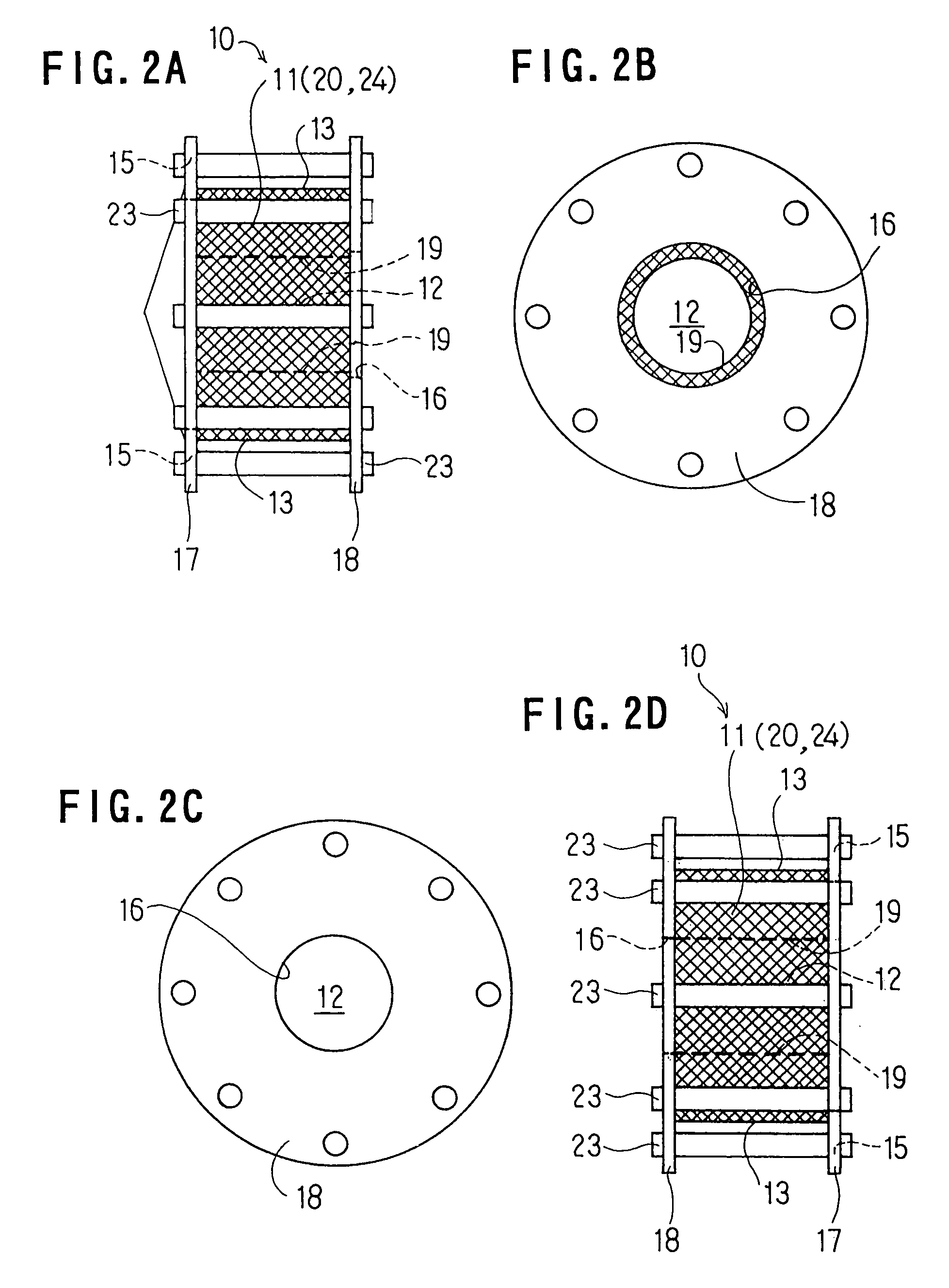
[0166]Shape of each filter 11: outer diameter of 250 mm; inner diameter of 90 mm; and thickness of 40 mm.

[0167]Specification of each filter 11: two kinds of filters were used: (1) a filter 11 of which the diameter of the wire 20 is 0.5 mm and the filling density thereof is 25%; (2) a filter 11 of which the diameter of the wire 20 is 0.35 mm and the filling density thereof is 31%.

[0168]Type of a diesel engine 9: a normal aspiration engine of ...

embodiment 2

[0173]Tests on the second embodiment will now be described with reference to FIG. 4B. In this second embodiment, a bench test was conducted for a pressure loss using three kinds of filters 11 in which the combination specification of the diameter of the wire 20 and the filling density thereof differs while changing the number of superpositions (laminations), respectively. Test conditions are based on the first embodiment.

[0174]As a result, the measurement results as shown in FIG. 4B were obtained, whereby it was verified that the pressure loss varies with the specification of each filter 11 used even in the case of the same filter surface area. In other words, when the diameter of the wire 20 and the filling density thereof differ, the cubic volume of the filter 11 differs and thus, the pressure loss was different.

[0175]For example, in the case where two filters 11 of which the diameter of the wire 20 is 0.35 mm and the filling density thereof is 31%, were used, the surface area of ...

embodiment 3

[0177]Tests on the third embodiment will now be described with reference to FIG. 4C. In this third embodiment, a bench test was conducted for the reduction and purification rate (the collection rate) using one kind of filter 11 in the cases where only the filter 11 is used, where the filter 11 is used with the oxidation catalyst 24, and where the filter 11 is used with the oxidation catalyst 24 and the fuel borne catalyst 25 together, respectively, while changing the number of superpositions (laminations) of the filter 11. The test conditions are based on the first and second embodiments described above.

[0178]As a result, the measurement results as shown in FIG. 4C were obtained. In each case, the more the number of superpositions and the wider the surface area of the filter 11, the higher the reduction and purification rate (the collection rate). When observed in the range of a collection rate (reduction and purification rate) of 20% to 50% in the case where only the filter 11 is u...


PUM

PropertyMeasurementUnit
diameteraaaaaaaaaa
sizeaaaaaaaaaa
sizeaaaaaaaaaa

Abstract

This particulate matter reducing apparatus 10 is provided to burn and reduce particulate matter (“PM”) in an exhaust gas 1 of a diesel engine while collecting the PM on each filter 11 at a low collection rate of 50% or less in total. The filter 11 is composed of a wire mesh structure and is formed in a short column shape provided with a central through hole 12. The filter 11 is coaxially housed in an outer cylindrical casing 4 with a gap 14 provided within the casing and is retained by a pair of front and rear shielding plates 17 and 18. The pair of shielding plates 17 and 18 divides the inside of the outer cylindrical casing 4 in front and rear and is provided with one or more air holes 15 and 16 at the outer circumferential section or at the central section.

Description

BACKGROUND OF THE INVENTION[0001]1. Field of the Invention[0002]The present invention relates to an apparatus for reducing particulate matter. More particularly, the present invention relates to a particulate matter reducing apparatus which can collect, burn and reduce the particulate matter contained in an exhaust gas of a diesel engine. For example, the present invention relates to a reducing apparatus which can be additionally mounted later on an existing car which is being used.[0003]2. Description of the Art[0004]An exhaust gas of a diesel engine contains CO, HC, NOx, Particulate matter and the like. If directly discharged to the open air, these are harmful to the human body and the environment. It is therefore an important theme to reduce these harmful substances.[0005]The present invention therefore relates to a particulate matter reducing apparatus for reducing the particulate matter among these harmful substances.[0006]FIG. 5 is an explanatory cross-sectional view of a conv...

Claims


Application Information

Patent Timeline
Patent Type & Authority Patents(United States)
IPC IPC(8): B01D46/02F01N3/023F02M27/02B01D39/14B01D39/20B01D46/24B01D46/42C10L1/12C10L10/00C10L10/02C10L10/06F01N3/02F01N3/021F01N3/022F01N3/035F01N13/02F01N13/04
CPCC10L1/1208C10L10/02C10L10/06F01N3/0217F01N3/0226F01N3/023F01N3/035F01N13/00F01N13/017F01N13/0097F01N2330/12F01N2470/08F01N2470/20Y10S55/30Y10S55/10F16K1/223F16K27/0218F16K1/54
Inventor TOYODA, TETSUROMATSUOKA, KATSUNORI
Owner CLEAN DIESEL TECHNOLOGIES
Why Eureka
Try Eureka