
Methods and systems for automated fingerprint recognition

a fingerprint recognition and fingerprint technology, applied in the field of fingerprint recognition technology, can solve the problems of inability to reach the correct conclusion, conventional algorithms used by computers, and low matching score achievable by conventional fingerprint recognition techniques in comparison with certain other biometric technologies

Inactive Publication Date: 2009-01-06
CHAU LAM KO
View PDF24 Cites 65 Cited by
  • Summary
  • Abstract
  • Description
  • Claims
  • Application Information

AI Technical Summary

Problems solved by technology

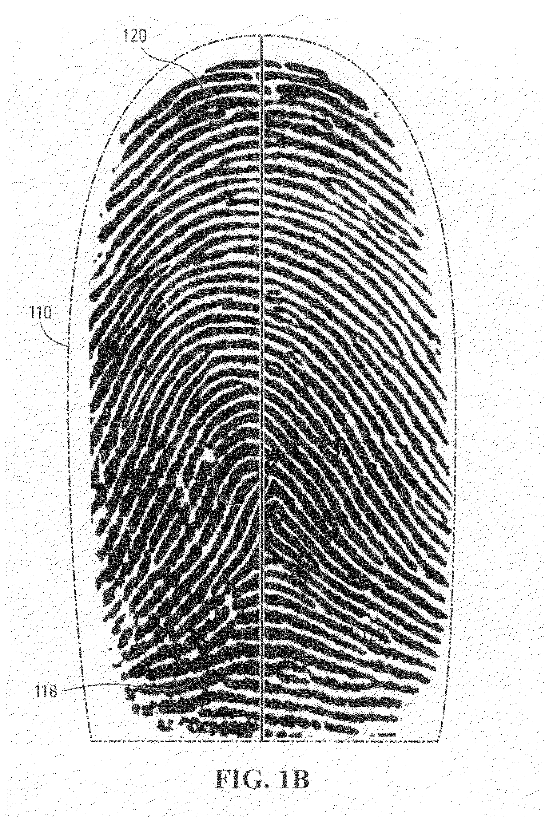
Firstly, conventional algorithms used by computers to conclude whether or not there is a “match” between a subject fingerprint image and a reference fingerprint image tend to fail to reach the correct conclusion in cases where the subject fingerprint image exhibits an unstable pattern of minutiae.
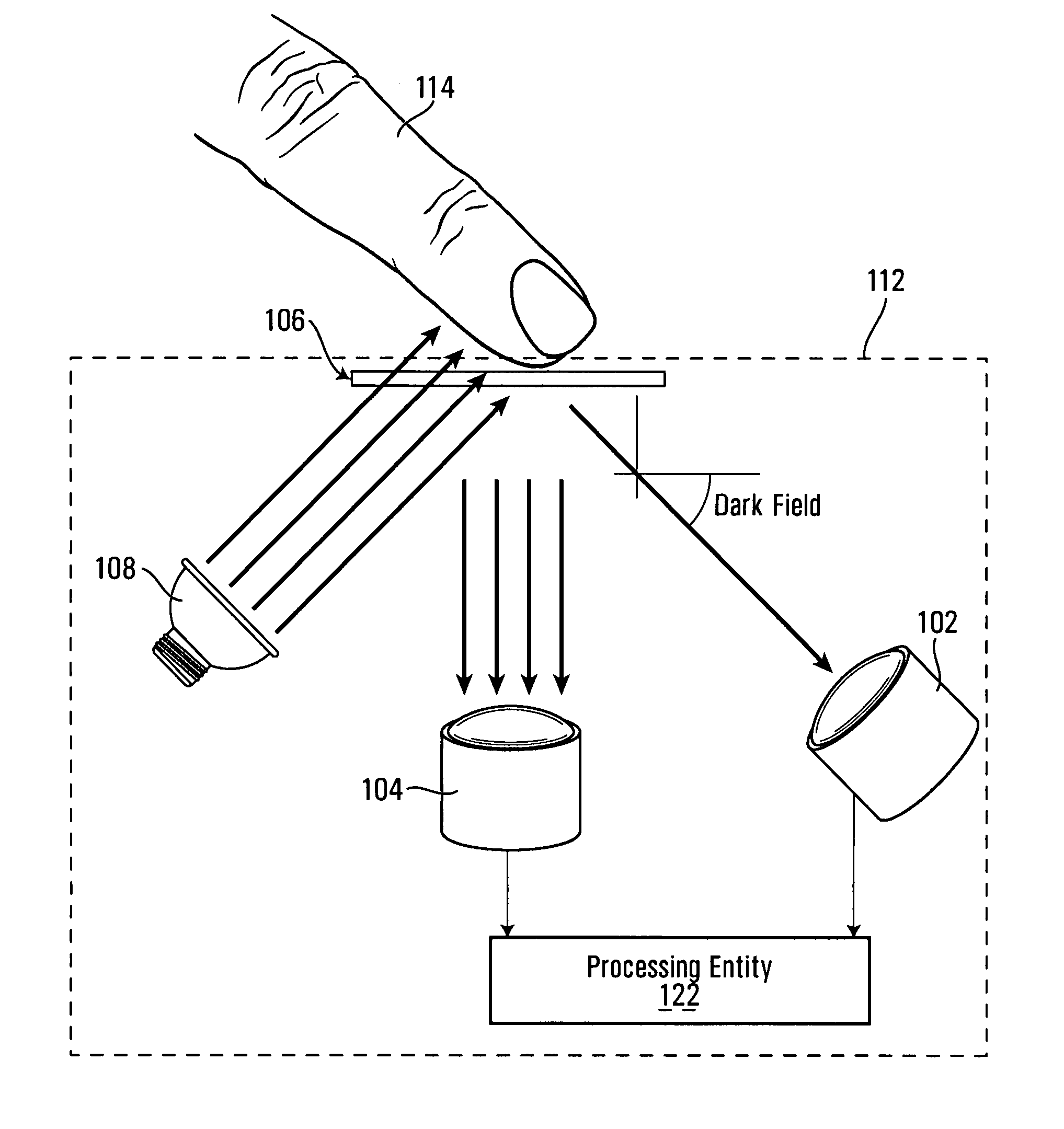
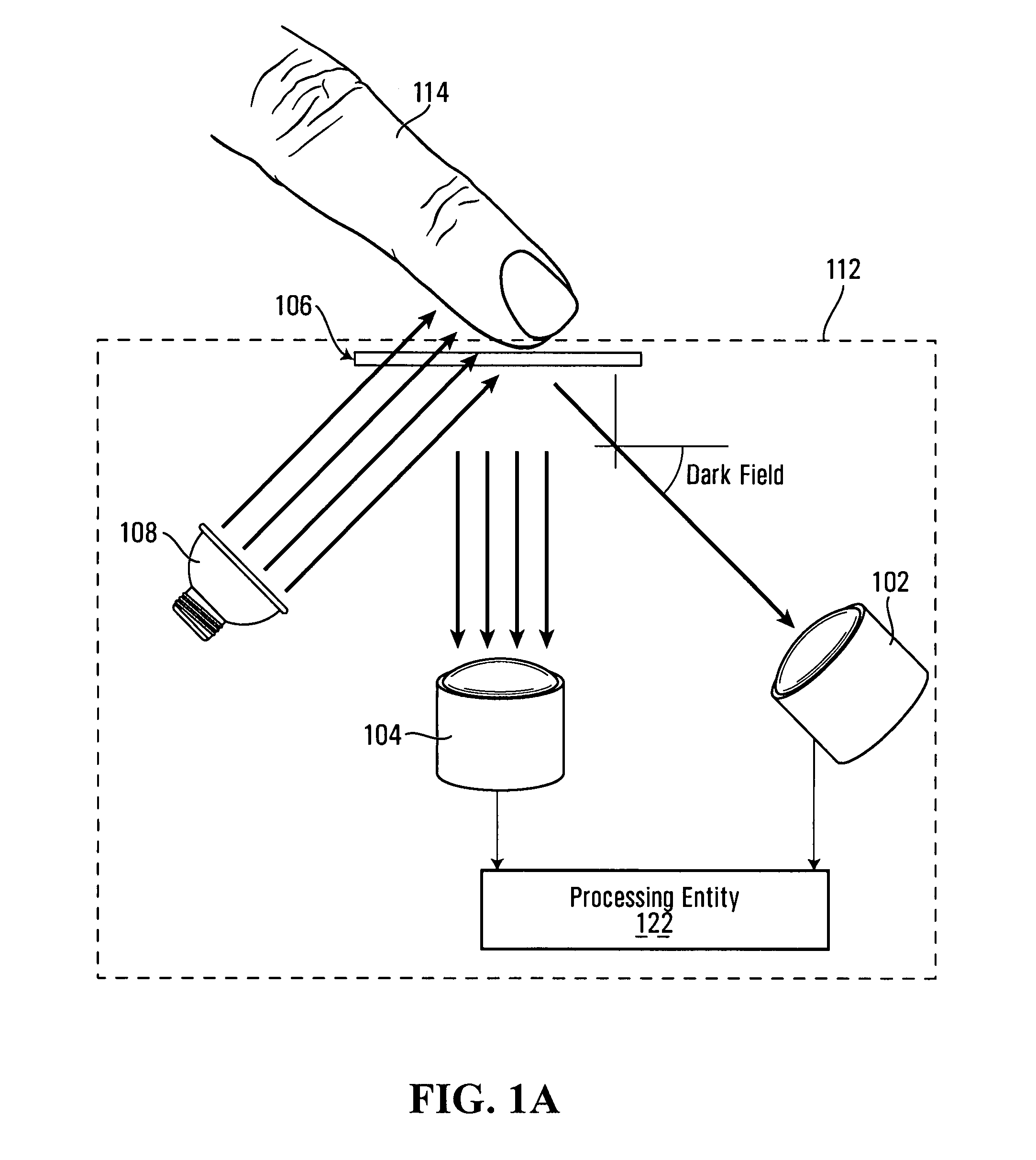
Such instability arises largely due to the necessity of having a thin liquid layer on top of the fingertip (and, notably, within the valleys of the epidermis of the fingertip) to provide continuity for light wave propagation in so-called dark field image acquisition.
This instability renders the matching score achievable by conventional fingerprint recognition techniques low in comparison with certain other biometric technologies, such as iris scan, for example.
Secondly, recognizing that many fingerprint images available today for comparison were taken at some time in the past, it will be appreciated that such images cannot realistically be re-captured and re-entered into a database.
Thus, depending on the conditions under which such “legacy” fingerprint images were taken, they may not be in an ideal coordinate system for reliable machine comparison relative to a subject fingerprint image.
This again leads to the instability issue mentioned above as well as other problems.

Method used


Image

  • Methods and systems for automated fingerprint recognition
  • Methods and systems for automated fingerprint recognition
  • Methods and systems for automated fingerprint recognition

Examples


Embodiment Construction

[0027]The fingerprint recognition process comprises two main phases, namely an enrollment phase and an active phase. During the enrollment phase, a database of records is populated with fingerprint data regarding a plurality of persons of interest, for eventual comparison with fingerprint data obtained from a subject during the active phase. Enrollment of persons of interest may be done by processing live-scan fingerprint images (obtained in situ) or by processing legacy fingerprint images, such as inked impressions, obtained previously.

[0028]With reference to FIG. 2, there is shown a database 26, which comprises a plurality of records 28. The database 26 may be centralized (as in a fingerprint repository) or distributed (as in a plurality of fingerprint scanners). For instance, where the application at hand involves attempting to determine a subject's presence on an international no-fly list, the database 26 may span the intelligence services of multiple countries. Alternatively, w...


PUM


Abstract

A method of identifying a donor of a fingerprint image exhibiting a pattern of minutiae. The method comprises deriving a donor index code and a donor match code associated with the donor fingerprint image. A database of records is accessed—each record being associated with an identity and indicative of a respective index code and a respective match code—in an attempt to identify at least one record for which the respective index code corresponds to the donor index code. Responsive to the attempt being successful, it is determined whether any of these “candidate” records includes a particular record for which the respective match code corresponds to the donor match code. Upon indeed determining that this is so for a particular record, an output is generated, such output being indicative of a conclusion that the donor of the fingerprint image has the identity associated with the particular record.

Description

CROSS REFERENCE TO RELATED APPLICATIONS[0001]The present application is a continuation of U.S. patent application Ser. No. 11 / 706,644, filed on Feb. 14, 2007 (now U.S.Pat. No. 7,327,859), the contents of which are incorporated by reference herein.FIELD OF THE INVENTION[0002]The present invention relates generally to fingerprint recognition technology and, more specifically, to methods and systems for automated fingerprint recognition.BACKGROUND OF THE INVENTION[0003]The need to identify and authenticate individuals is greater today than it has ever been, and is particularly acute for applications such as homeland security, law enforcement, electronic commerce, access control and privacy protection, to name a few.[0004]The use of biometrics in general, and fingerprint recognition in particular, to identify and authenticate humans is a proven method that dates back several centuries. However, to perform identification and authentication in many of the applications envisaged today, spe...

Claims


Application Information

Patent Timeline
Patent Type & Authority Patents(United States)
IPC IPC(8): G06K9/00
CPCG06K9/00046G06K9/00093G06V40/1371G06V40/1324
Inventor CHAU, LAM KO
Owner CHAU LAM KO
Learn More