Display unit with processor and communication controller which communicates information to the processor
a display unit and processor technology, applied in the direction of instruments, electric digital data processing, cathode-ray tube indicators, etc., can solve the problems of not being able to obtain the status simply desired by the user, troublesome operation of the system, and inability to adjust the image to the display image, etc., to achieve easy maintenance, maintain the secrecy of information, and reduce power consumption
- Summary
- Abstract
- Description
- Claims
- Application Information
AI Technical Summary
Benefits of technology
Problems solved by technology
Method used
Image
Examples
first embodiment
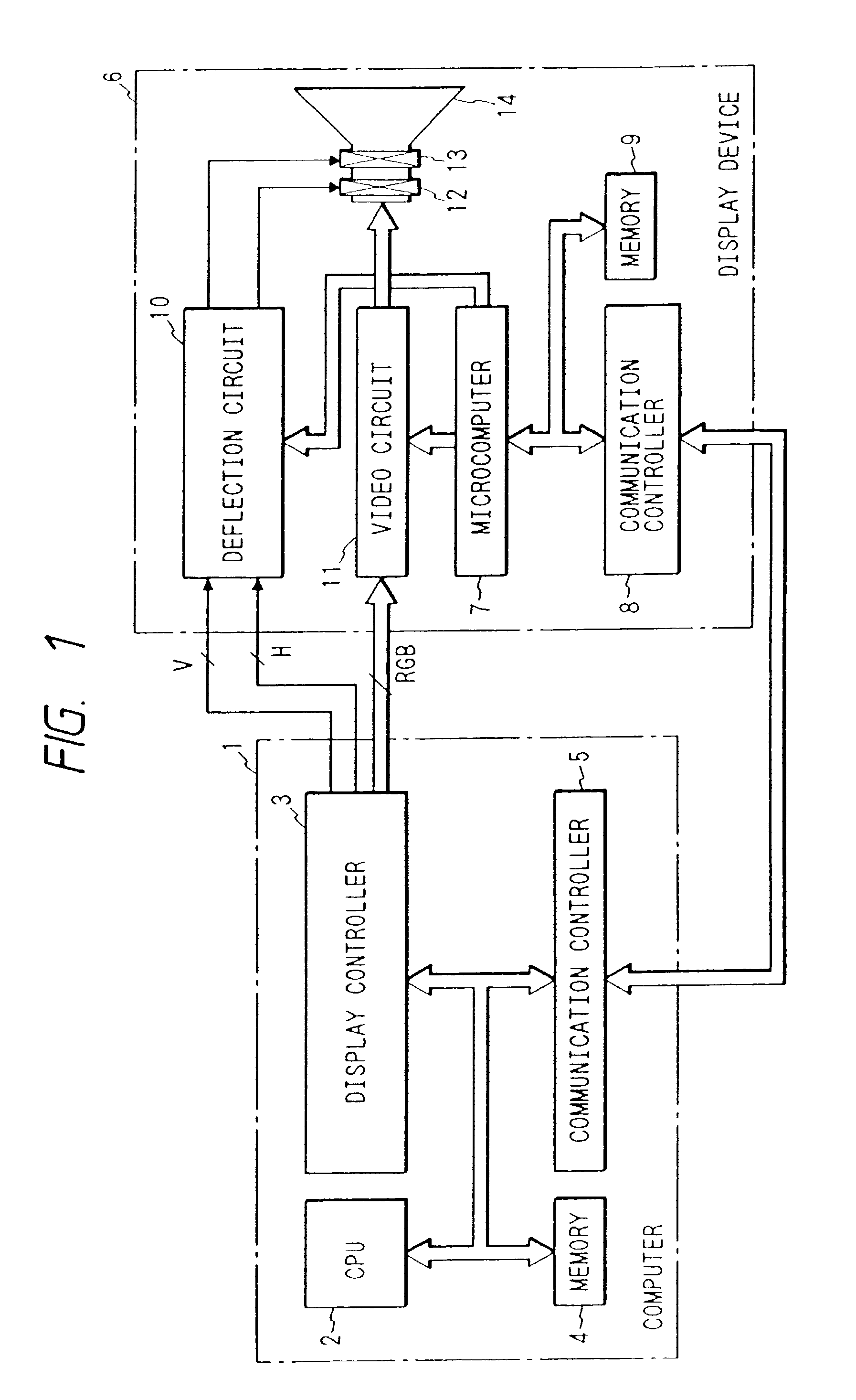
[0029]FIG. 1 is a block diagram showing the present invention. In the drawing, a section 1 enclosed by a chained line indicates a computer. In the section 1, a reference numeral 2 indicates a CPU (central processing unit), 3 a display controller for generating various signals for video display, 4 a memory, and 5 a communication controller for communicating with peripheral devices. In addition, a magnetic recording unit is mounted as a data storage device which is not shown in the drawing.
[0030]A section 6 enclosed by another chained line indicates a so-called multi-scan display device which can be applied to various video signal specifications. In the section 6, a reference numeral 7 indicates a microcomputer for controlling display of the display device 6, 8 a second communication controller for communicating with the above communication controller 5, 9 a second memory, 10 a general deflection circuit of the display device, 11 a video circuit of the display device, 12 a horizontal ...
third embodiment
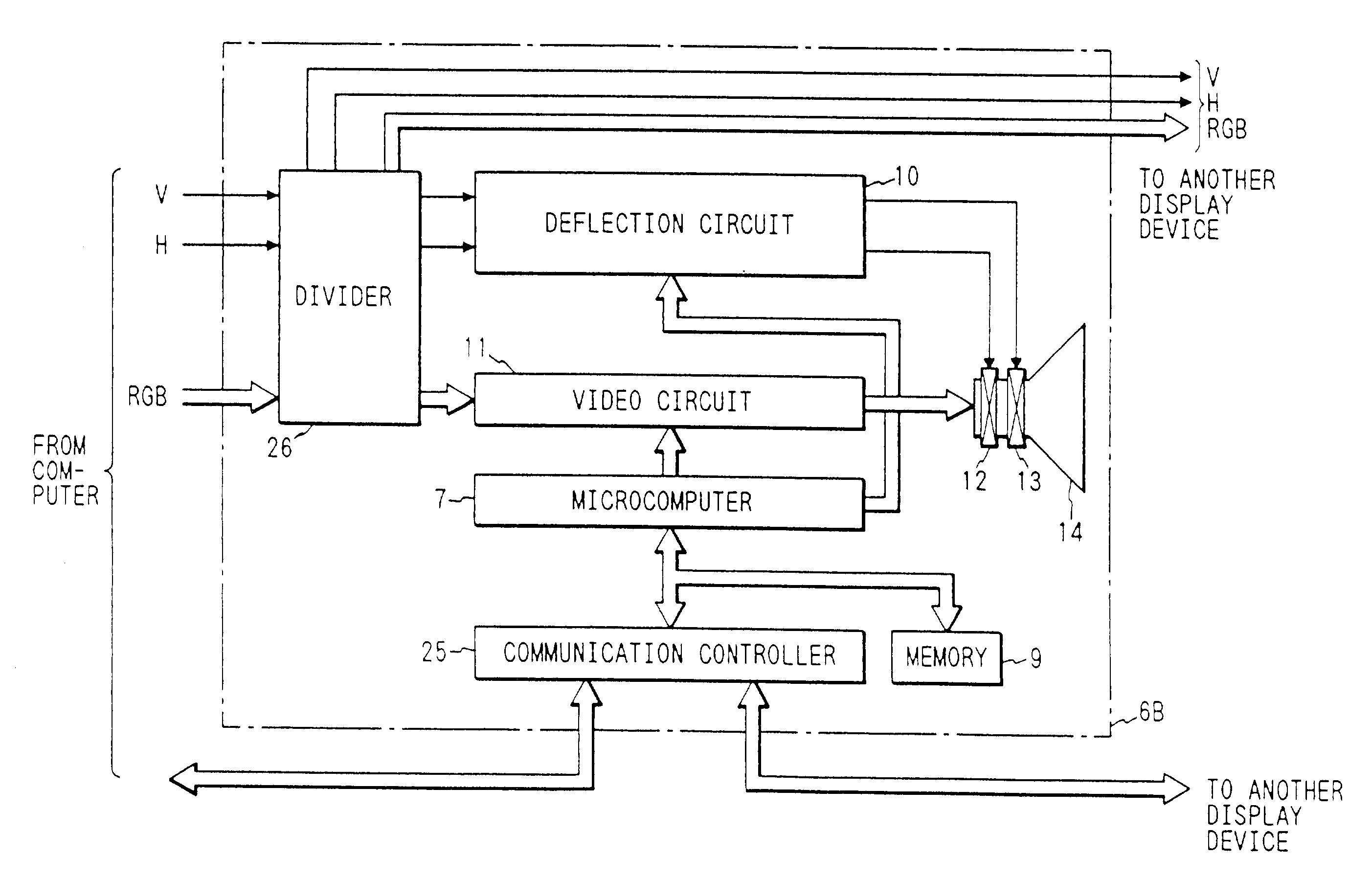
[0047]FIG. 5 is a block diagram of the present invention. According to this embodiment, the display device is provided with a plurality of communication functions and a plurality of display devices can be connected with the communication interface. In the drawing, reference numerals 6B, 6C, and 6D indicate display devices having the same structure, V1, V2, and V3 lines for video signals and synchronizing signals, C1, C2, and C3 communication lines for, for example, RS-232C, and 1 the aforementioned computer. Each of the display devices 6B, 6C, and 6D has a plurality of video signal I / O terminals and communication interface I / O terminals and a registered ID number. According to this embodiment, as shown in FIG. 5, 1 is assigned to the display device 6B as an ID number, 2 to the display device 6C as an ID number, and 3 to the display device 6D as an ID number.
[0048]Next, the operation shown in FIG. 5 will be explained. In the drawing, for example, when controlling the display device 6...
fifth embodiment
[0057]FIG. 9 is a block diagram showing the present invention. This embodiment obtains the same effect as that of the embodiment shown in FIG. 7. In FIG. 9, a reference numeral 6F indicates a display device, 33 a liquid crystal display controller in the display device 6F, and 34 a liquid crystal display panel mounted in the display device 6F. The other reference numerals which are the same as those shown in FIGS. 1 and 7 indicate the same functions.
[0058]The operation shown in FIG. 9 is basically the same as that shown in FIG. 7. The operation of the deflection circuit 10 or video circuit 11 is monitored by the microcomputer 7 via the ADC 27 or 28. When an error occurs, the microcomputer 7 transmits an indication code informing the occurrence of an error to the computer 1B via the communication line and informs the user of it by voice from the speaker 32.
[0059]Furthermore, the microcomputer 7 allows the liquid crystal display controller 33 in the display device 6F to operate and dis...
PUM
 Abstract
Description
Claims
Application Information
 - R&D
- Intellectual Property
- Life Sciences
- Materials
- Tech Scout
- Unparalleled Data Quality
- Higher Quality Content
- 60% Fewer Hallucinations
Browse by: Latest US Patents, China's latest patents, Technical Efficacy Thesaurus, Application Domain, Technology Topic, Popular Technical Reports.
© 2025 PatSnap. All rights reserved.Legal|Privacy policy|Modern Slavery Act Transparency Statement|Sitemap|About US| Contact US: help@patsnap.com


