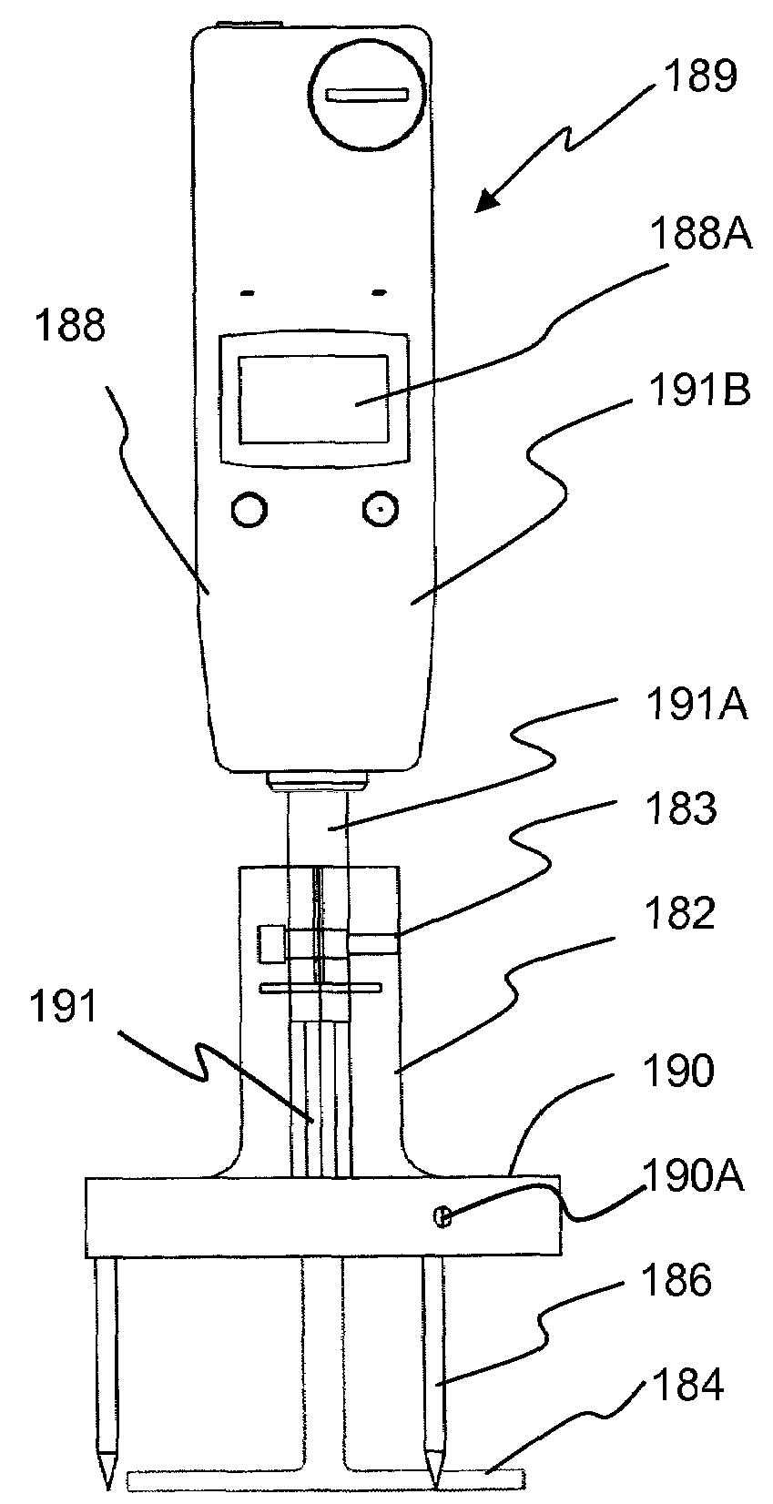
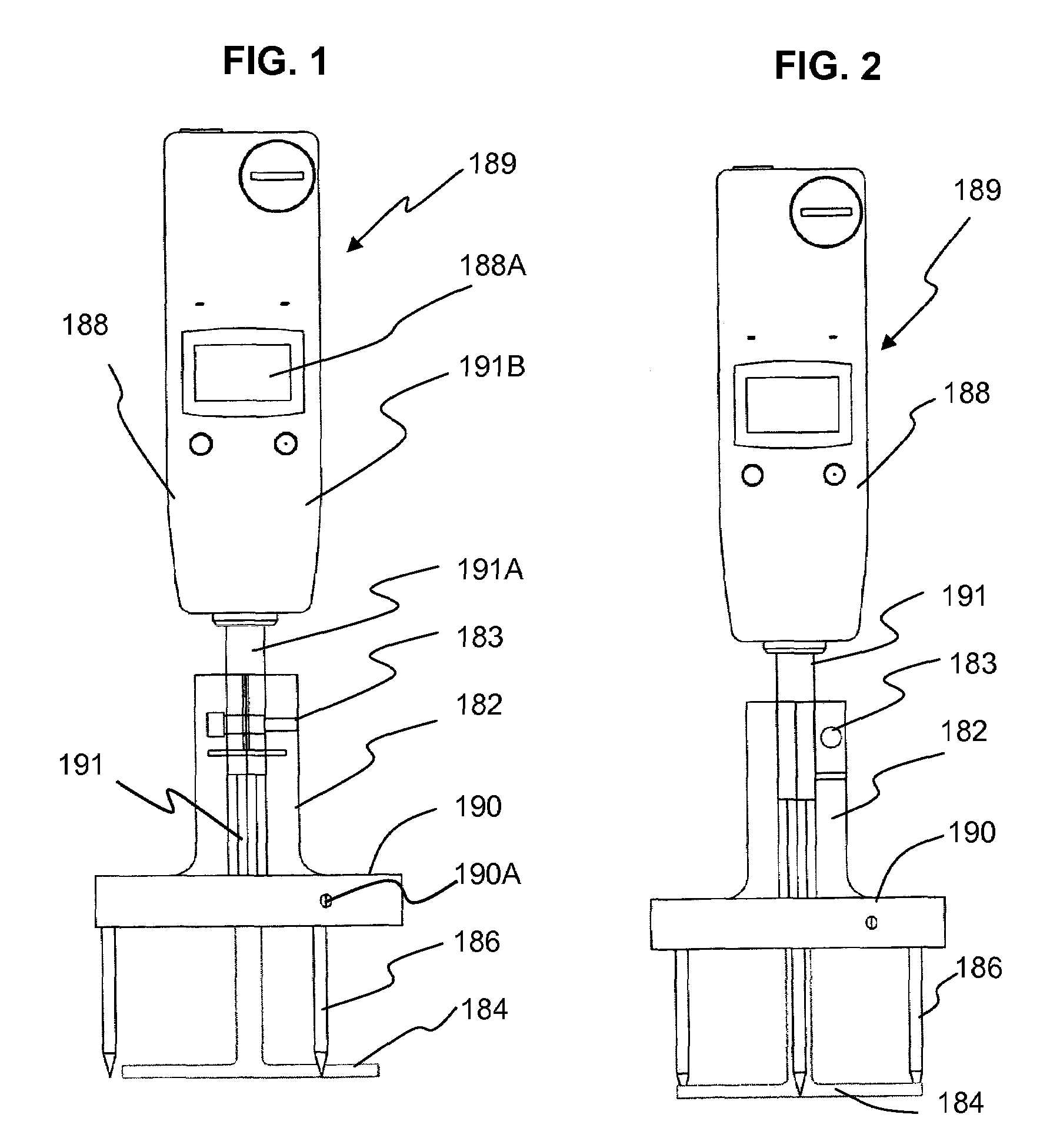
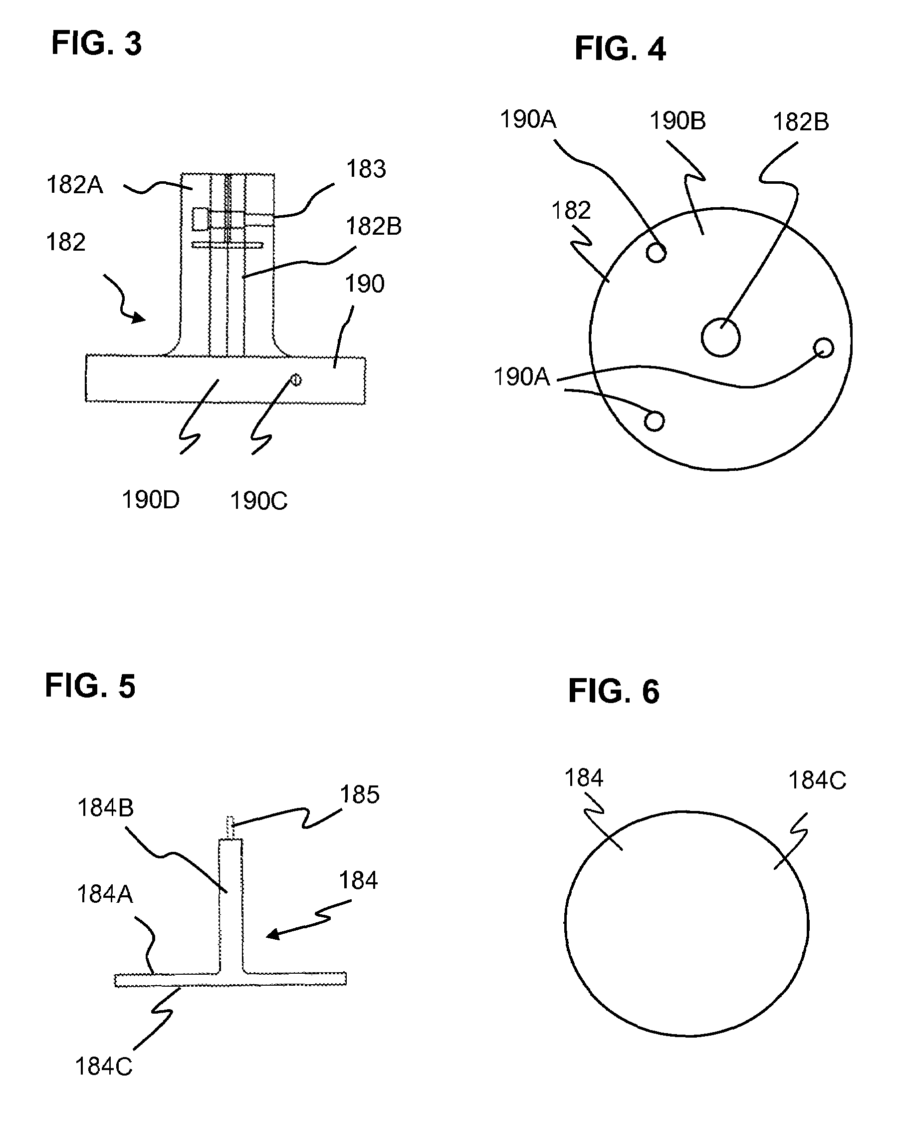
Wet slurry thickness gauge and method for use of same

a technology of wet slurry and thickness gauge, which is applied in the direction of instruments, mechanical measuring arrangements, liquid/fluent solid measurement, etc., can solve the problem of insufficient structural strength

Inactive Publication Date: 2009-01-13
UNITED STATES GYPSUM CO
View PDF64 Cites 18 Cited by
  • Summary
  • Abstract
  • Description
  • Claims
  • Application Information

AI Technical Summary

Benefits of technology

[0020]The unique design of the instant handheld thickness gauge allows for a pre-set to measure the exact thickness of the slurry layer in real time without having the thickness gauge spindle sinking into the slurry layer.
[0023]The thickness gauge is advantageous for reliably measuring thickness of slurry layers, prior to the setting of the slurry, to assist in quality control.
[0024]For example, the thickness gauge is useful to measure thickness of a slurry panel on a production line, prior to setting, to assist in quality control in a multi-layer process for producing structural cementitious panels (SCP's or SCP panels). In a process for making SCP panels, after one of an initial deposition of loosely distributed, chopped fibers or a layer of slurry upon a moving web, fibers are deposited upon the slurry layer. An embedment device thoroughly mixes the recently deposited fibers into the slurry so that the fibers are distributed throughout the slurry, after which additional layers of slurry, then chopped fibers are added, followed by more embedment. The process is repeated for each layer of the panel, as desired. Upon completion, the board has a more evenly distributed fiber component, which results in relatively strong panels without the need for thick mats of reinforcing fibers, as are taught in prior art production techniques for cementitious panels.
[0025]In a preferred embodiment, of the process multiple layers of chopped individual loose fibers are deposited relative to each layer of deposited slurry. The typical sequence is that a layer of loose fibers are deposited, upon either the moving web or existing slurry, followed by a layer of slurry, then another layer of fibers. Next, the fiber / slurry / fiber combination is subjected to embedding to thoroughly mix the fibers in the slurry. This procedure has been found to permit the incorporation and distribution of a relatively larger amount of slurry fibers throughout the slurry using fewer slurry layers. Thus, panel production equipment and processing time can be reduced, while providing an SCP panel with enhanced strength characteristics.
[0028]The present wet slurry thickness gauge can assist in quality control of the above processes by providing accurate reliable thickness measurements of the slurry panels prior to their setting.

Problems solved by technology

However, a drawback of such conventional panels is that they do not have sufficient structural strength to the extent that such panels may be comparable to, if not stronger than, structural plywood or oriented strand board (OSB).

Method used


Image

  • Wet slurry thickness gauge and method for use of same
  • Wet slurry thickness gauge and method for use of same
  • Wet slurry thickness gauge and method for use of same

Examples


second embodiment

of a Production Line

[0122]The present metering gauge may also be used with an alternate SCP panel production line or system 130 illustrated in FIG. 12 and generally designated 130 for producing high-performance, fiber reinforced SCP panels incorporating a relatively high volume of fibers per slurry layer.

[0123]In many cases, increased levels of fibers per panel are obtained using this system. While the system of FIG. 10 discloses depositing a single discrete layer of fibers into each subsequent discrete layer of slurry deposited after the initial layer, the production line 130 includes a method of building up multiple discrete reinforcing fiber layers in each discrete slurry layer to obtain the desired panel thickness. Most preferably, the disclosed system embeds at least two discrete layers of reinforcing fibers, in a single operation, into an individual discrete layer of slurry. The discrete reinforcing fibers are embedded into the discrete layer of slurry using a suitable fiber e...


PUM

PropertyMeasurementUnit
diameteraaaaaaaaaa
diameteraaaaaaaaaa
diameteraaaaaaaaaa

Abstract

A handheld wet slurry thickness gauge and method for its use. The thickness gauge includes a distance displacement measurement gauge, a skirt, a platen and support legs. The distance displacement measurement gauge includes a case, a vertical stem, and a vertical spindle. The stem extends from the case. The spindle is slidably supported to move in an axial direction within the stem. The case body has a display for indicating a linear displacement of the spindle. The skirt has a central through-hole for receiving the stem of the gauge and retaining the stem in an upright position. The measuring platen has a platen base and a platen shaft extending upwardly from the platen base and attached to the spindle. The support legs extend downwardly from the skirt. The platen is below the skirt.

Description

CROSS REFERENCE TO RELATED APPLICATIONS[0001]This application is related to co-pending:[0002]U.S. patent application Ser. No. 11 / 555,647, entitled PROCESS AND APPARATUS FOR FEEDING CEMENTITIOUS SLURRY FOR FIBER-REINFORCED STRUCTURAL CEMENT PANELS, filed Nov. 1, 2006;[0003]U.S. patent application Ser. No. 11 / 555,655, entitled METHOD FOR WET MIXING CEMENTITIOUS SLURRY FOR FIBER-REINFORCED STRUCTURAL CEMENT PANELS, filed Nov. 1, 2006;[0004]U.S. patent application Ser. No. 11 / 555,658, entitled APPARATUS AND METHOD FOR WET MIXING CEMENTITIOUS SLURRY FOR FIBER-REINFORCED STRUCTURAL CEMENT PANELS, filed Nov. 1, 2006;[0005]U.S. patent application Ser. No. 11 / 555.661, entitled PANEL SMOOTHING PROCESS AND APPARATUS FOR FORMING A SMOOTH CONTINUOUS SURFACE ON FIBER-REINFORCED STRUCTURAL CEMENT PANELS, filed Nov. 1, 2006;[0006]U.S. patent application Ser. No. 11 / 591,793, entitled MULTI-LAYER PROCESS AND APPARATUS FOR PRODUCING HIGH STRENGTH FIBER-REINFORCED STRUCTURAL CEMENTITIOUS PANELS WITH EN...

Claims


Application Information

Patent Timeline
Patent Type & Authority Patents(United States)
IPC IPC(8): G01B7/16G01F25/00G01L1/00
CPCG01B5/061
Inventor FRANK, WILLIAM A.UNDERKOFLER, ABRAHAM M.RAGO, WILLIAM J.
Owner UNITED STATES GYPSUM CO
Why Eureka
Try Eureka