
Clip-based fastening arrangement for attaching multi-pin connector to rear panel of electronic equipment chassis

a technology of electronic equipment chassis and clip-based fastening, which is applied in the direction of electrical equipment, substation/switching arrangement details, coupling device connections, etc., can solve the problems of structural rigidity, difficult and cumbersome access to attachment fittings, and disrupt the service of its associated telecommunication circuit, etc., to achieve stable capture and structural robust

Active Publication Date: 2009-01-13
ADTRAN
View PDF6 Cites 0 Cited by
  • Summary
  • Abstract
  • Description
  • Claims
  • Application Information

AI Technical Summary

Benefits of technology

The present invention provides a solution for attaching a multi-pin connector to a printed circuit card by using a physically robust clip. This clip allows for the secure and stable insertion of a standard multi-pin connector into a connector-installation aperture on a rear panel without the need for a hardware fitting attachment bore. The clip is made of a solid material, such as aluminum, which provides stability and durability. This invention eliminates the need for flimsy attachment devices and ensures the proper connection between the multi-pin connector and the rear panel.

Problems solved by technology

This is particularly problematic as cable and circuit densities have increased, making access to attachment fittings difficult and cumbersome.
Unfortunately, removing the rear panel in order to attach such a connector means that any other printed circuit card, to which another respective connector supported by that rear panel is connected, will necessarily be taken off-line, and thereby disrupt service to its associated telecommunication circuit.
Drawbacks of these approaches include their inherent lack of structural rigidity, their inability to ensure blind alignment between the multi-pin connector and its associated multi-socket receptacle on the printed circuit card, and the fact that they are labor intensive, which increases the cost of manufacture.

Method used


Image

  • Clip-based fastening arrangement for attaching multi-pin connector to rear panel of electronic equipment chassis
  • Clip-based fastening arrangement for attaching multi-pin connector to rear panel of electronic equipment chassis
  • Clip-based fastening arrangement for attaching multi-pin connector to rear panel of electronic equipment chassis

Examples


Embodiment Construction

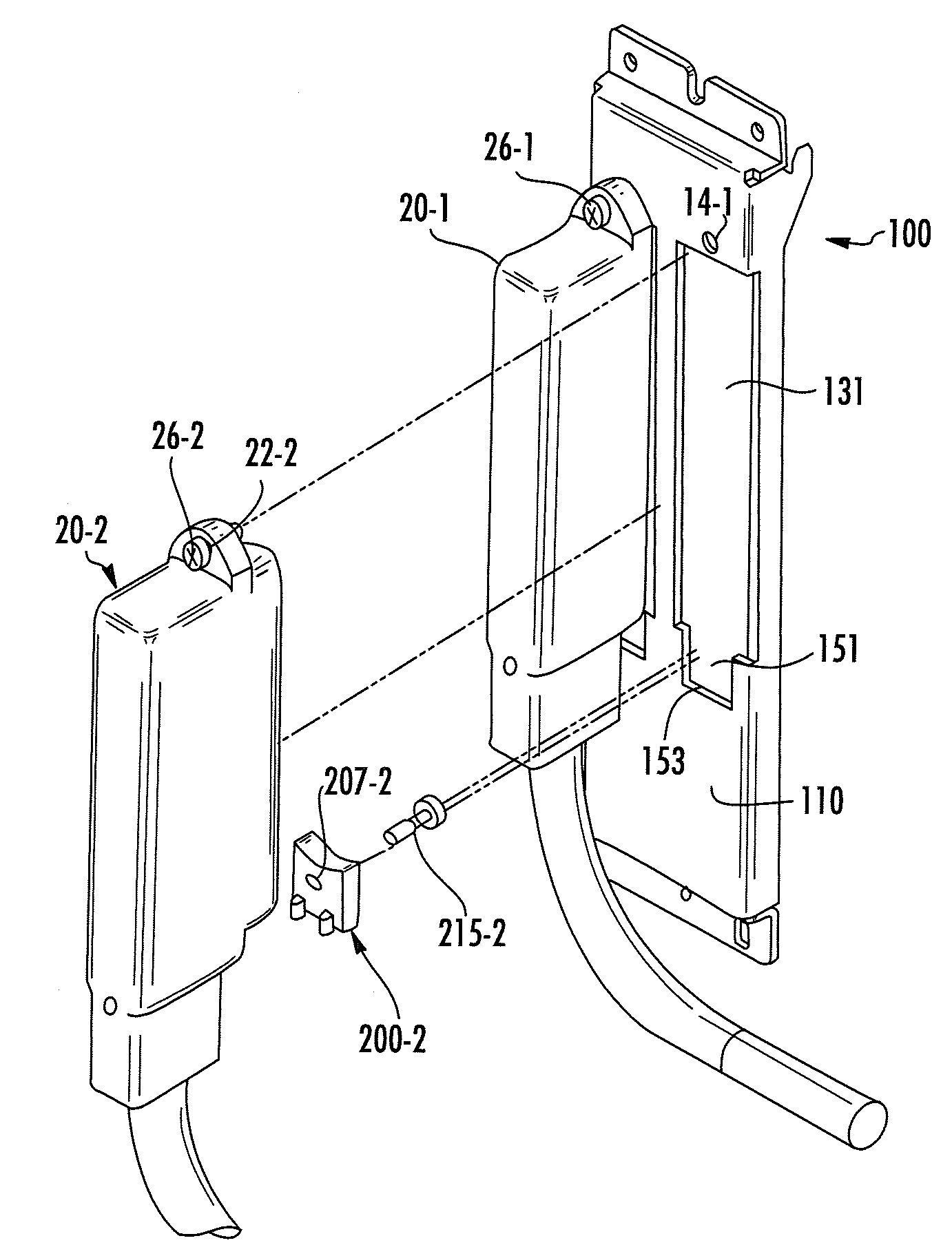
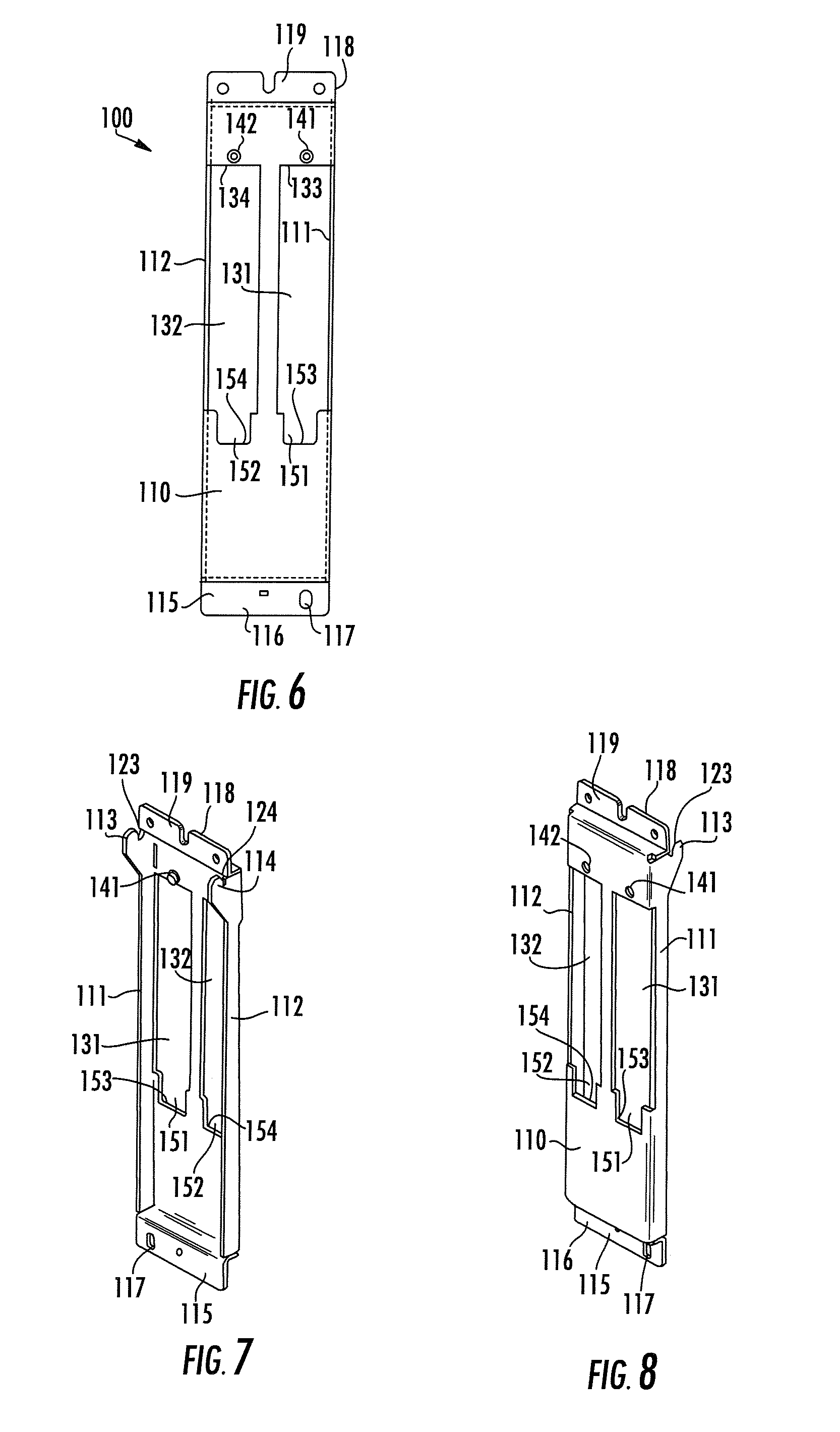
[0015]Attention is now directed to FIGS. 6, 7 and 8, which are respective front, front perspective and rear perspective diagrammatic views of the configuration of a rear panel employed in the multi-pin connector attachment arrangement of the present invention. As shown therein, the rear panel 100 includes a generally planar or flat, rectangular faceplate 110, from parallel side edges of which extend respective sidewalls 111 and 112. Upper ends of the sidewalls terminate at respective flange portions 113 and 114. Extending from a lower edge of the faceplate 110 is a generally L-shaped lower bend portion 115, having a lower lip portion 116 that is generally coplanar with the longitudinal edges of sidewalls 111 and 112 and includes a slot 117, that is sized to receive a fitting, such as a screw and the like, for attaching the lower bend portion 115 of the rear panel 100 to a corresponding bore in a generally horizontally extending frame member of a telecommunication equipment rack (suc...


PUM


Abstract

A clip is attachable to a flange of a connector terminating an electrical cable, and is configured to mechanically couple one side of the flange to an edge of a connector-installation aperture of a chassis, such that a distal end of the connector may engage a receptacle within the chassis. When the connector, with the clip attached, is placed in the chassis' connector-installation aperture, a notch region of the clip engages the chassis at an edge of its connector-installation aperture, causing a bore on a second side of the flange to be coaxial with a bore in the chassis, so that a hardware fitting therethrough may secure the connector to the chassis.

Description

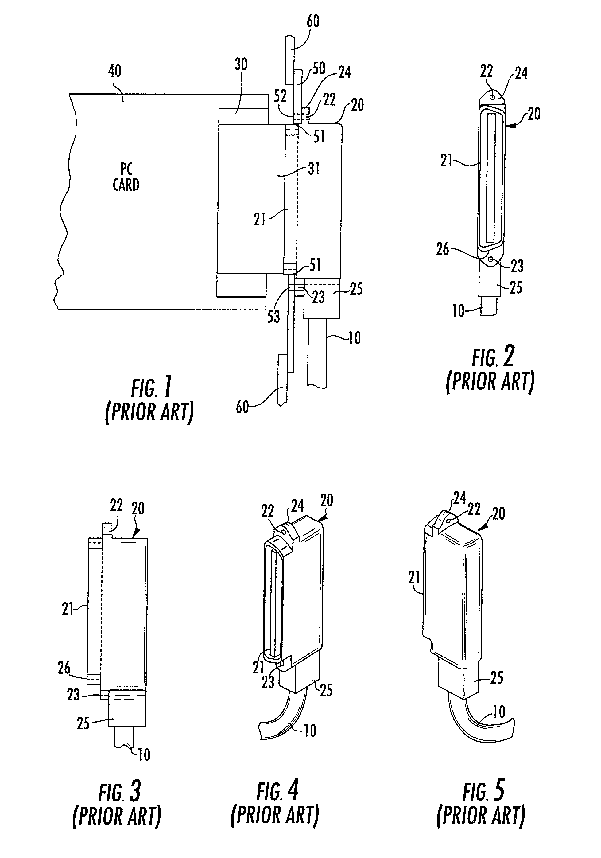
FIELD OF THE INVENTION[0001]The present invention relates in general to electronics (e.g., telecommunications) equipment and components thereof, and is particularly directed to a clip-based fastening arrangement for facilitating aligned ‘blind’ insertion and attachment of a multi-pin communication cable connector, such as, but not limited to a ‘telco’-type multi-pin connector, into a connector-installation aperture of a (rear) panel of an equipment chassis, so that the pins of the connector may readily electrically and mechanically engage corresponding sockets of an associated multi-socket receptacle of a printed circuit board installed in a card slot adjacent to the rear panel of the chassis.BACKGROUND OF THE INVENTION[0002]A variety of electronics systems, such as telecommunication systems, commonly employ multi-conductor cables to provide electrical connections to system components, such as, but not limited, to circuit components mounted on printed circuit cards installed within ...

Claims


Application Information

Patent Timeline
Patent Type & Authority Patents(United States)
IPC IPC(8): H01R13/73
CPCH01R13/748
Inventor CARDEN, SCOTT L.
Owner ADTRAN
Learn More