
Fuel cell system

Active Publication Date: 2009-01-13
TOYOTA JIDOSHA KK
View PDF7 Cites 7 Cited by
  • Summary
  • Abstract
  • Description
  • Claims
  • Application Information

AI Technical Summary

Benefits of technology

[0007]An object of the present invention is to provide a technology that can judge whether or

Problems solved by technology

In this type of fuel cell system, when the ambient temperature goes down to sub-zero while the system stops operating for a while, water inside the fuel cell system may freeze, resulting in a impediment to operation.
Further, there is also the possibility that this freezing might degrade the fuel cell system.
There is a chance, however, that the range a water level sensor can detect water will be limited.
For example, when the quantity of accumulated water is small, there is a chance that water level sensor may not be able to detect the water.
In this case, there is a possibility that water may not be detected and remain in the water trap.
As a result, when there is a large quantity of accumulated water, the opening time of the discharge port will be insufficient, resulting in substantial quantity of water being left in the water trap.

Method used


Image

  • Fuel cell system
  • Fuel cell system
  • Fuel cell system

Examples


first embodiment

A. First Embodiment

[0028]A1. System Configuration

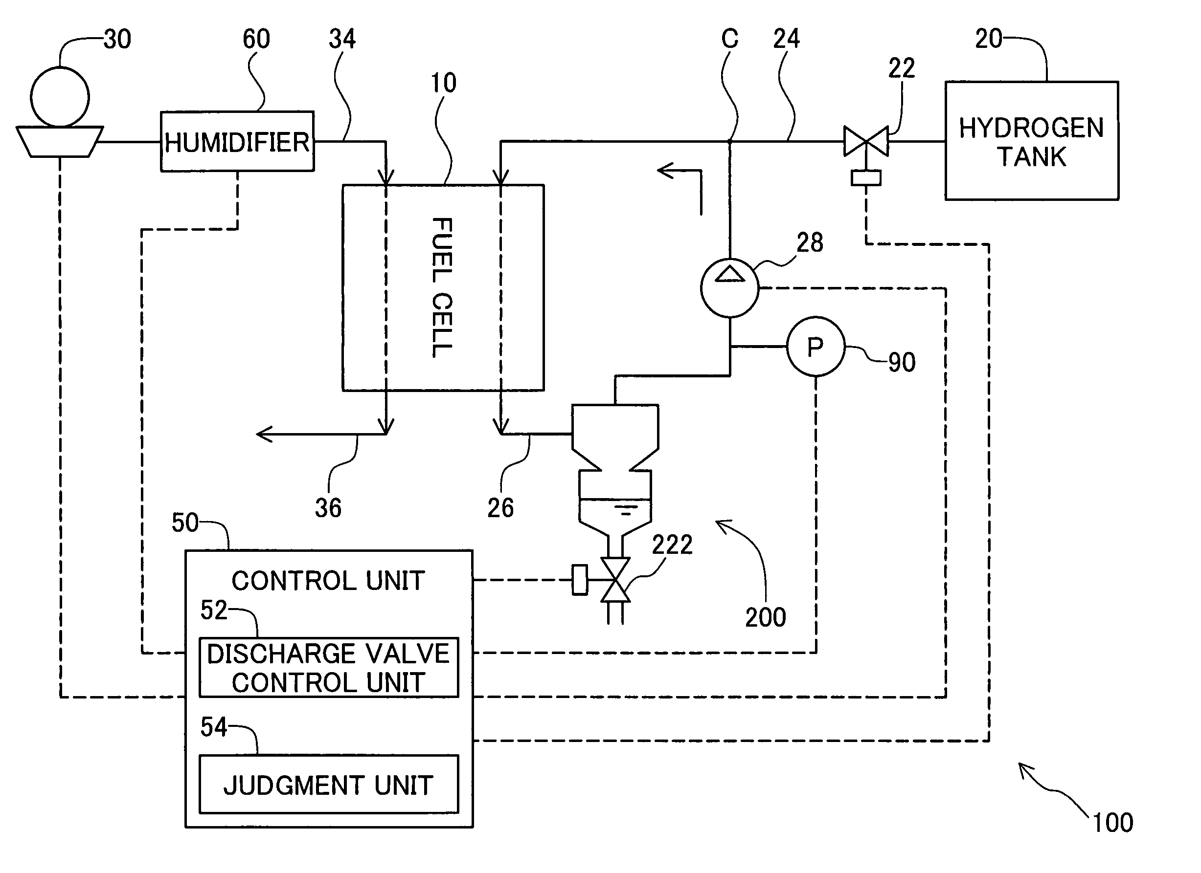
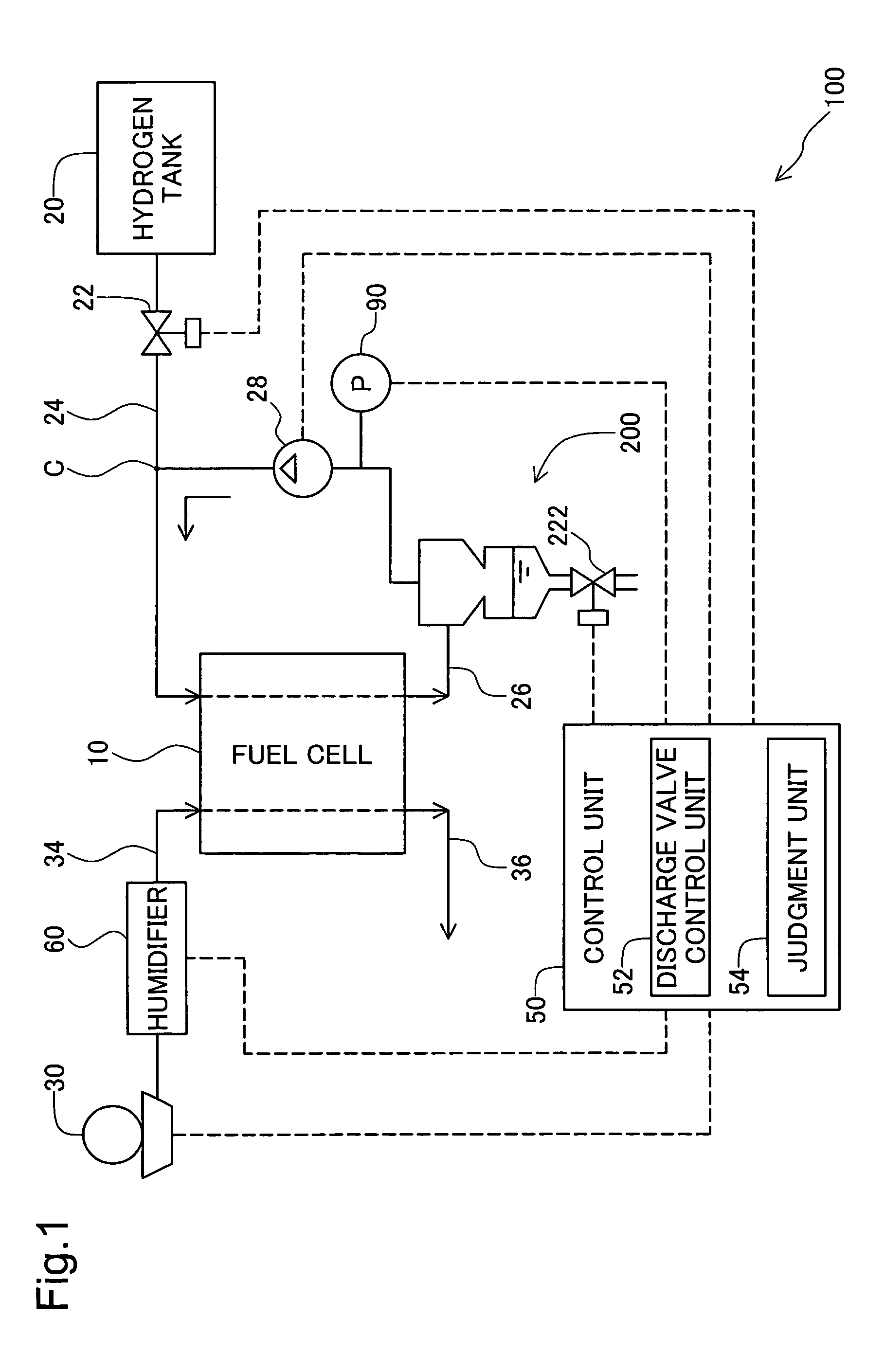
[0029]FIG. 1 is a block diagram showing the configuration of the fuel cell system 100 as an embodiment of the present invention. This fuel cell system 100 comprises a fuel cell 10, a hydrogen tank 20, a blower 30, a control unit 50, a water trap 200, and a pressure sensor 90.

[0030]The fuel cell 10 is of a solid polymer electrolyte type and has a stack of a plurality of single cells. Each single cell is comprised of an electrolyte inserted between a hydrogen electrode (anode) and an oxygen electrode (cathode). An electrochemical reaction occurs between a fuel gas that contains hydrogen supplied to the anode and an oxygen gas supplied to the cathode, thereby generating an electromotive force. The electrical power generated in the fuel cell 10 is supplied to a designated load (not shown in the drawing) connected to the fuel cell 10. In addition to the solid polymer electrolyte type, various types of fuel cells can be used for the fuel ce...

second embodiment

B. Second Embodiment

[0069]In the first embodiment described above, the discharge quantity of the anode discharge gas during the discharge operation may be adjusted higher as the impurity concentration becomes higher. In the first discharge process mode shown in FIG. 4, the discharge quantity of the anode discharge gas can be adjusted by adjusting the discharge time T1 when the discharge valve 222 (FIGS. 1, 2) is open.

[0070]FIG. 6 shows an example of the relationship between the impurity concentration and the discharge time T1 in the second embodiment. The horizontal axis shows the impurity concentration at the time of the discharge operation, and the vertical axis shows the discharge time T1. It is possible to avoid excessive discharge of hydrogen gas by making the discharge time T1 relatively short and making the discharge quantity of the anode discharge gas relatively small when the impurity concentration is relatively low in this manner. Further, it is also possible to prevent th...

third embodiment

C. Third Embodiment

[0073]FIG. 7 is a timing chart describing the operation of the second discharge process mode as another example of the discharge process of step S120 in the water trap control routine shown in FIG. 3. The difference from the first discharge process mode shown in FIG. 4 is that the discharge valve 222 opens and then closes in response to the judgment unit 54 establishing a “judgment that water is not accumulated” in the second discharge process mode.

[0074]In the example of FIG. 7, the discharge valve control unit 52 (FIG. 1) opens the discharge valve 222 (FIG. 2, FIG. 5) at timing te. Water accumulated in the water trap 200 is discharged through the open discharge valve 222 accordingly. The pressure inside the anode discharge gas flow passage 26 drops from an operating pressure Pd2 by a relatively small degree along with the discharge of the water. The operating pressure Pd2 depends on the magnitude of the load on the fuel cell.

[0075]When the water inside the water...


PUM


Abstract

A water trap having a discharge valve is disposed in a gas flow passage of a fuel cell system. It is judged whether or not water is accumulated inside the water trap based on pressure variation inside the gas flow passage when the discharge valve is kept open.

Description

BACKGROUND OF THE INVENTION[0001]1. Field of the Invention[0002]The present invention relates to discharge of impurities in a fuel cell system for generating electricity by means of an electrochemical reaction between hydrogen and oxygen.[0003]2. Description of the Related Art[0004]In recent years attention has been focused on fuel cells that generate electricity by means of an electrochemical reaction between hydrogen and oxygen as an energy source. In this type of fuel cell system, when the ambient temperature goes down to sub-zero while the system stops operating for a while, water inside the fuel cell system may freeze, resulting in a impediment to operation. Further, there is also the possibility that this freezing might degrade the fuel cell system. There has been proposed a water trap for temporarily accumulating water and then discharging the accumulated water from a discharge port of the water trap to the outside (for example, JP2002-313403A).[0005]It is preferable to disch...

Claims


Application Information

Patent Timeline
IPC IPC(8): H01M8/00H01M8/02H01M8/04H01M8/10H01M8/06
CPCH01M8/04089H01M8/04164Y02E60/50
Inventor FUJITA, NOBUO
Owner TOYOTA JIDOSHA KK
Features
  • Generate Ideas
  • Intellectual Property
  • Life Sciences
  • Materials
  • Tech Scout
  • Unparalleled Data Quality
  • Higher Quality Content
  • 60% Fewer Hallucinations
Learn More