
Programmable automation controller assembly

a programmable logic controller and assembly technology, applied in the direction of electrical apparatus casings/cabinets/drawers, lighting conductor installation, coupling device connection, etc., can solve the problems of in-place field wiring disruption, many specifications become invalid, and the downtime involved, so as to reduce the disruption of in-field wiring and minimize system downtime

Active Publication Date: 2009-01-13
FAIRMONT AUTOMATION
View PDF10 Cites 8 Cited by
  • Summary
  • Abstract
  • Description
  • Claims
  • Application Information

AI Technical Summary

Benefits of technology

"The present invention provides an apparatus and method for a programmable logic controller that can be used in harsh environments. The apparatus includes a user-configurable module housed in a multi-purpose harsh environment enclosure. The module has a two-board design, an active board, and a wiring hub, all housed in a design that reduces the disruption to in-field wiring and minimizes system downtime. The enclosure is sealed to prevent leaks and can include various interface devices on the outside face. The method includes housing multiple user-configurable modules in an enclosure, locating an active electrical board on the inside face of the front cover, locating the wiring hub in the main body, and providing a label pocket on the outside face of the front cover that can withstand harsh environmental conditions. Overall, the invention allows for the programmable logic controller to be used in harsh environments while still being easily configurable and maintainable."

Problems solved by technology

Many of those specifications become invalid when the device is confined to a sealed box (for example the temperature specification must be de-rated, shock and vibration specifications are unknown, etc.).
However, the designer of the repackaged device must endure the cost to retest each appropriate specification to ensure the product will function as expected in harsh environments, and the cost of repackaging the standard PLC enclosure into a second rugged enclosure to obtain both the required functionality features of the user and to withstand the harsh environmental conditions.
There is also the added disruption to in-place field wiring and the down-time involved when replacing the internal wiring and electronics due to an electrical failure or change in user design.

Method used


Image

  • Programmable automation controller assembly
  • Programmable automation controller assembly
  • Programmable automation controller assembly

Examples


Embodiment Construction

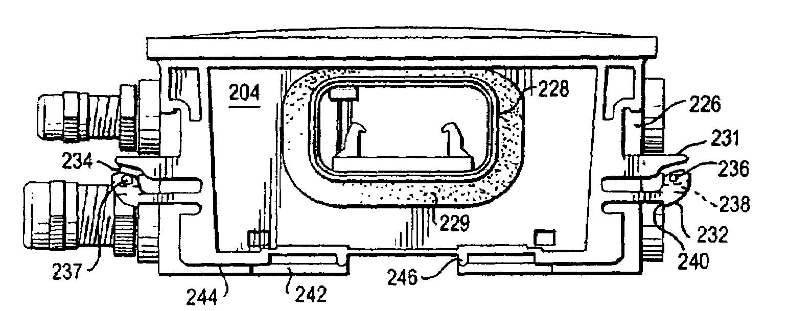
[0030]Turning to the drawings, FIG. 3 shows the controller assembly 100 of the present invention. The controller assembly 100 generally includes one or more modules or housings 102 and end caps 104. All of the interlocking parts are keyed to ensure they can only be assembled one way, which makes the assembly and maintenance of the controller assembly 100 very simple, yet rugged and able to withstand harsh environments. Any number of housings 102 can be added or removed from the controller assembly 100 on an as-needed basis. Accordingly, the size of the controller assembly 100 is modified based on the number of housings 102 that are mounted to one another based on the particular needs of the application. The two end caps 104 seal the left and right side of the assembly 100.

[0031]As best shown in FIGS. 5-6, the housings 102 each have a base 200 (FIG. 7) and a cover 300 (FIG. 8). The housings 102 are constructed of a hard polymer to withstand rugged environments and form a watertight e...


PUM


Abstract

A programmable logic controller or programmable automation controller assembly that can be used in harsh environments. A plurality of user-configurable housings are used to accommodate a customer's desired functionality design. A two-board design is featured to enable electronics in the controller assembly. The two-board design includes an active board that houses a majority of electrical components in the controller assembly, and a wiring hub that is used for wiring terminations. A mechanism is provided for a field-removable labeling system that withstands harsh environmental conditions.

Description

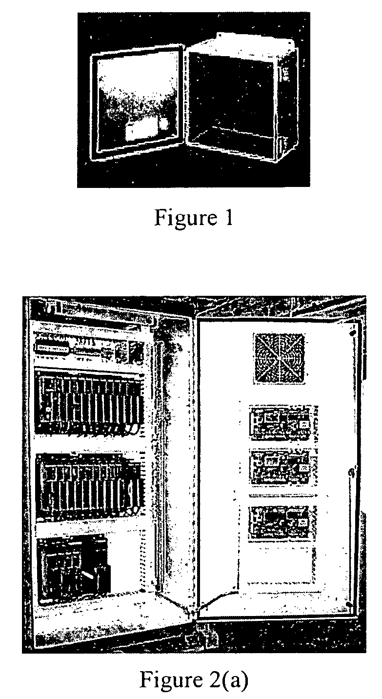
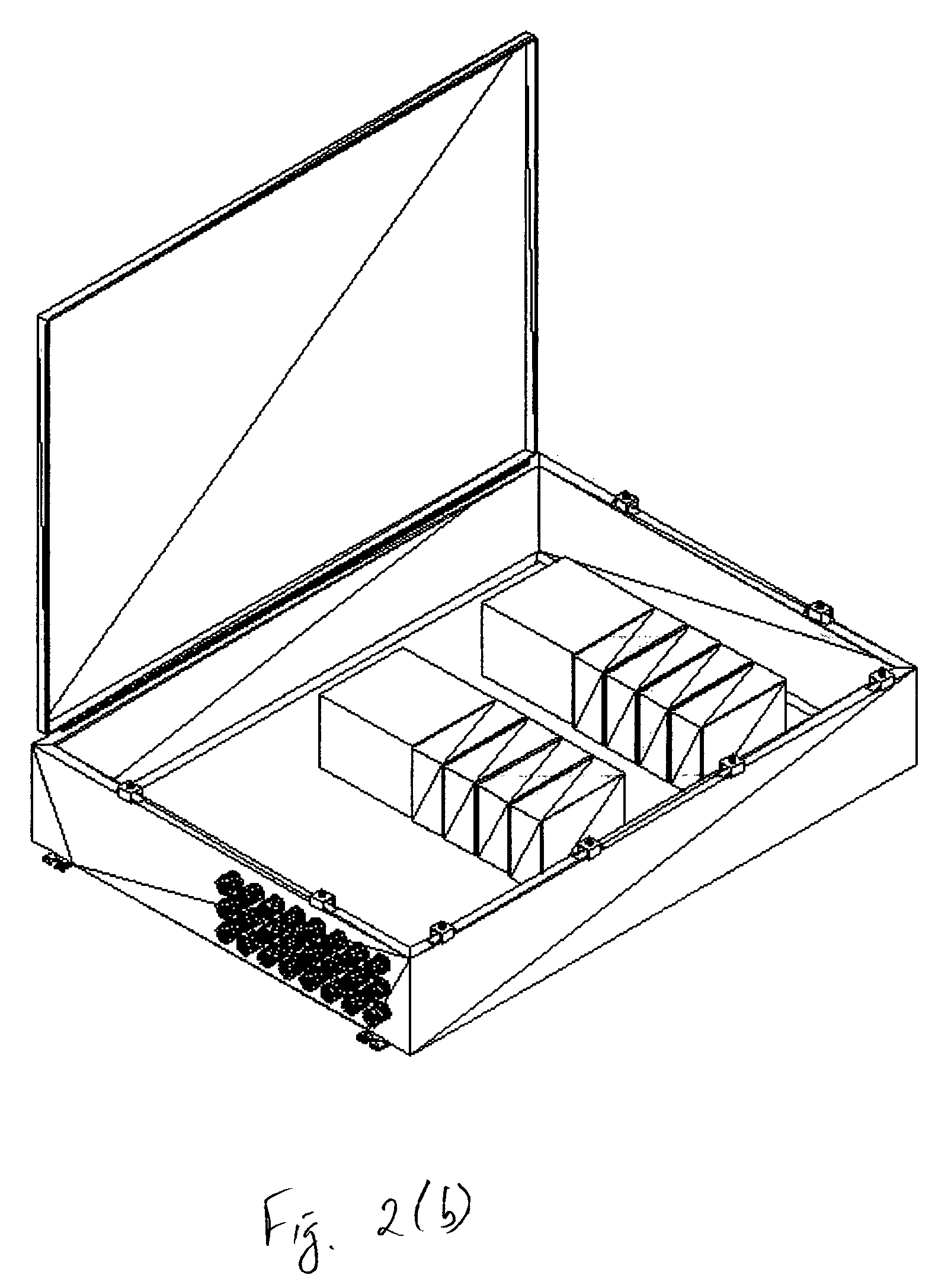
RELATED INVENTIONS[0001]The present application claims priority to U.S. Provisional Application Ser. No. 60 / 554,915, filed Mar. 22, 2004, the contents of which are incorporated herein by reference.FIELD OF THE INVENTION[0002]The present invention is generally related to programmable logic controllers and, more particularly, to an apparatus and method for a multi-purpose programmable logic controller that can be used in harsh environments.BACKGROUND OF THE INVENTION[0003]In order for most programmable logic controllers (PLCs) or programmable automation controller (PAC) to function in harsh environments they are required to be repackaged in a box similar to the one shown in FIGS. 1, 2a and 2b. Those boxes need the user to custom design the internal layout including wire ways, PLC mounting, wire penetrations, etc. In addition, PLC environmental specifications given by the manufacturer are typically listed for an open space with free-flowing air. Many of those specifications become inva...

Claims


Application Information

Patent Timeline
Patent Type & Authority Patents(United States)
IPC IPC(8): H01J5/00H03K19/177H05K5/06H05K7/14
CPCH05K5/061H05K7/1465H05K7/1474H05K7/1478
Inventor CANE, GARY R.CALLAHAN, BRIAN M.IOCCA, JAMES R.DIBONA, STEVE D.LEBAUDY, ANDRES
Owner FAIRMONT AUTOMATION
Learn More