Laser scanner
a laser scanner and scanner body technology, applied in the field of laser scanners, can solve problems such as image quality degradation, and achieve the effects of uniform sub-scanning magnification, reduced optical path length, and reduced device siz
- Summary
- Abstract
- Description
- Claims
- Application Information
AI Technical Summary
Benefits of technology
Problems solved by technology
Method used
Image
Examples
example 1
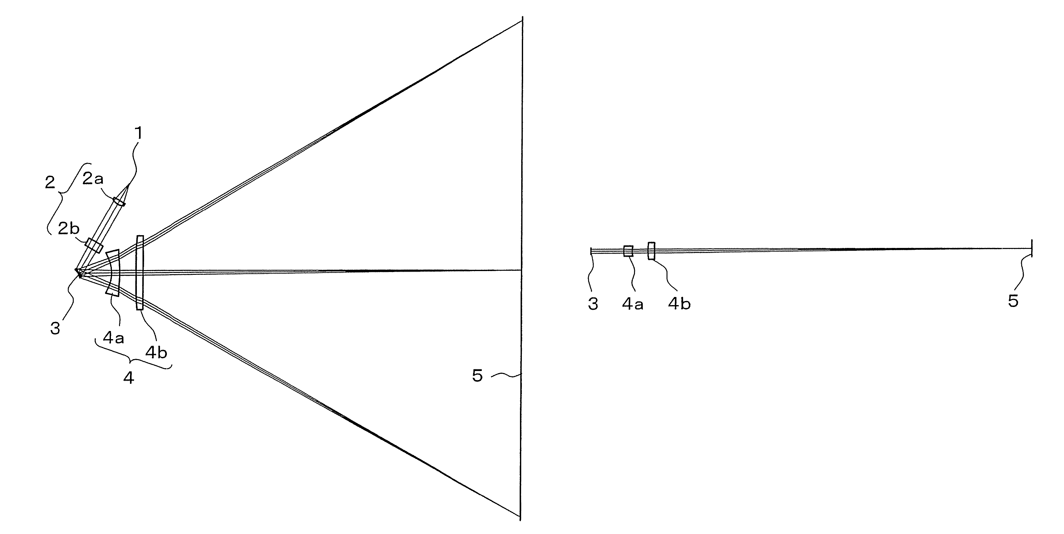
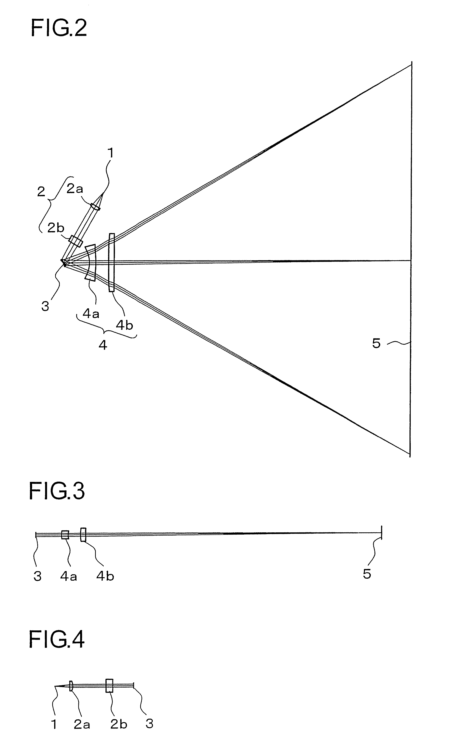
[0040]FIGS. 2 to 4 are optical path diagrams of a laser scanner according to Example 1. More specifically, FIG. 2 is an optical path diagram in the main-scanning cross section of the entire laser scanner. FIG. 3 is an optical path diagram showing the optical path in the sub-scanning cross section from the resonance mirror 3 to the photoconductor 5. FIG. 4 is an optical path diagram showing the optical path in the sub-scanning cross section from the light source 1 to the resonance mirror 3. In the main-scanning direction, light from the light source 1 turns to convergent light at the time when it is made incident on the resonance mirror 3.
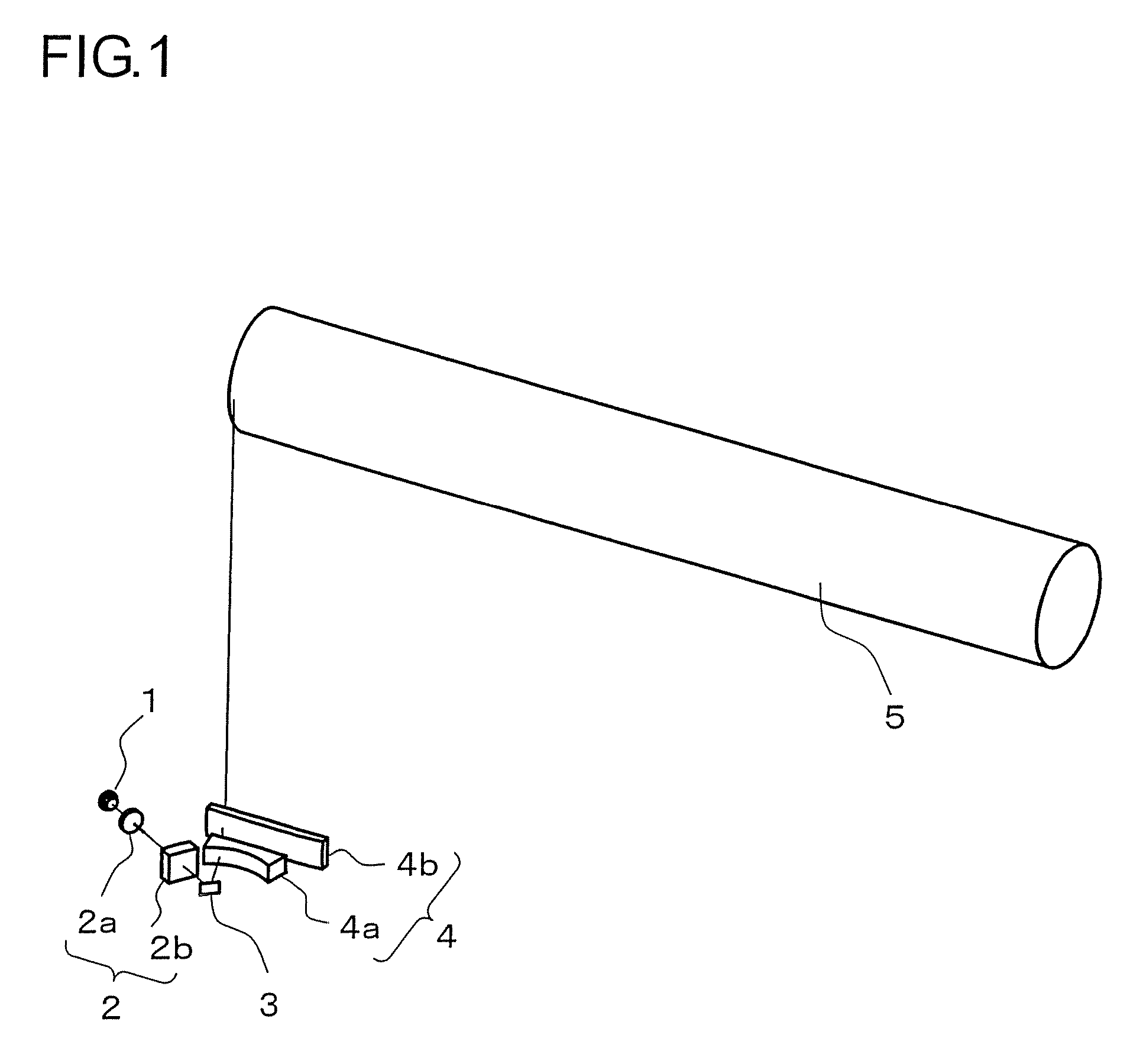
[0041]Here, in configuration for making convergent light incident on the resonance mirror 3, on the upstream side of the resonance mirror 3, the width (width in the main-scanning direction) of a flux of light increases with an increasing distance from the resonance mirror 3. Thus, an optical element (for example, a lens) arranged upstream of the res...
example 2
[0079]Next, a laser scanner of Example 2 will be described, FIGS. 13 to 15 are optical path diagrams of the laser scanner according to Example 2. More specifically, FIG. 13 is an optical path diagram in the main-scanning cross section of the entire laser scanner. FIG. 14 is an optical path diagram in the sub-scanning cross section from a resonance mirror 3 to a photoconductor 5. FIG. 15 is an optical path diagram in the sub-scanning cross section from a light source 1 to a resonance mirror 3. In FIG. 14, for a first lens 4a and a second lens 4b of a second optical system 4, only their light incidence side surfaces and light exit side surfaces are shown. Also in Example 2, in the main-scanning direction, light from the light source 1 turns into convergent light at the time when it is made incident on the resonance mirror 3.
[0080]Table 15 numerically shows coordinate data on optical surfaces of optical systems of Example 2.
[0081]
TABLE 15Local coordinateLocal coordinateLocal coordinate...
PUM
 Abstract
Description
Claims
Application Information
 - R&D
- Intellectual Property
- Life Sciences
- Materials
- Tech Scout
- Unparalleled Data Quality
- Higher Quality Content
- 60% Fewer Hallucinations
Browse by: Latest US Patents, China's latest patents, Technical Efficacy Thesaurus, Application Domain, Technology Topic, Popular Technical Reports.
© 2025 PatSnap. All rights reserved.Legal|Privacy policy|Modern Slavery Act Transparency Statement|Sitemap|About US| Contact US: help@patsnap.com


