Vibratory countermine system and method

a technology of vibratory excitation and mine detonation, which is applied in the field of vibratory countermine system and method, can solve the problems of large machine size, high maintenance cost, and high cost, and achieve the effect of increasing the stand-off distance for mine detonation, maximizing the magnitude and frequency of vibratory excitation, and maximizing the transmissibility into the soil

Inactive Publication Date: 2009-01-27
GSE TECH
View PDF28 Cites 8 Cited by
  • Summary
  • Abstract
  • Description
  • Claims
  • Application Information

AI Technical Summary

Benefits of technology

[0010]Against this background, it would be desirable to deploy a mobile, lightweight mine clearing system that is readily transportable, yet has increased mission effectiveness. To increase mission effectiveness, a desirable propulsion means will be self-protective as well as mine-clearing capable.
[0011]Another object of the invention is to provide a low-cost, self-contained system that will be affordable in third-world countries. Preferably, the system could be pushed by a security vehicle, a person, dilapidated commercial trucks, or even oxen—termed collectively herein as “propulsion means”.

Problems solved by technology

Flail systems have achieved greater success than tilling devices, but have flaws.
These machines are large, expensive, and difficult to maintain.
Maintenance costs are high, since chains or other ground-beating members are usually destroyed by landmines and must be replaced frequently.
But these machines are large and some weigh as much as 45 tons.
Typical systems tend to be very heavy and require a powerful prime mover.
Current systems are very large, expensive, and heavy.
This reduces the agility, transportability, and efficiency of deployed units.
These, among other conventional mine countermeasures, require significant tractive effort, thus forcing them to rely on large prime movers such as tanks, or even requiring the use of specialized vehicles.

Method used


Image

  • Vibratory countermine system and method
  • Vibratory countermine system and method
  • Vibratory countermine system and method

Examples


Embodiment Construction

)

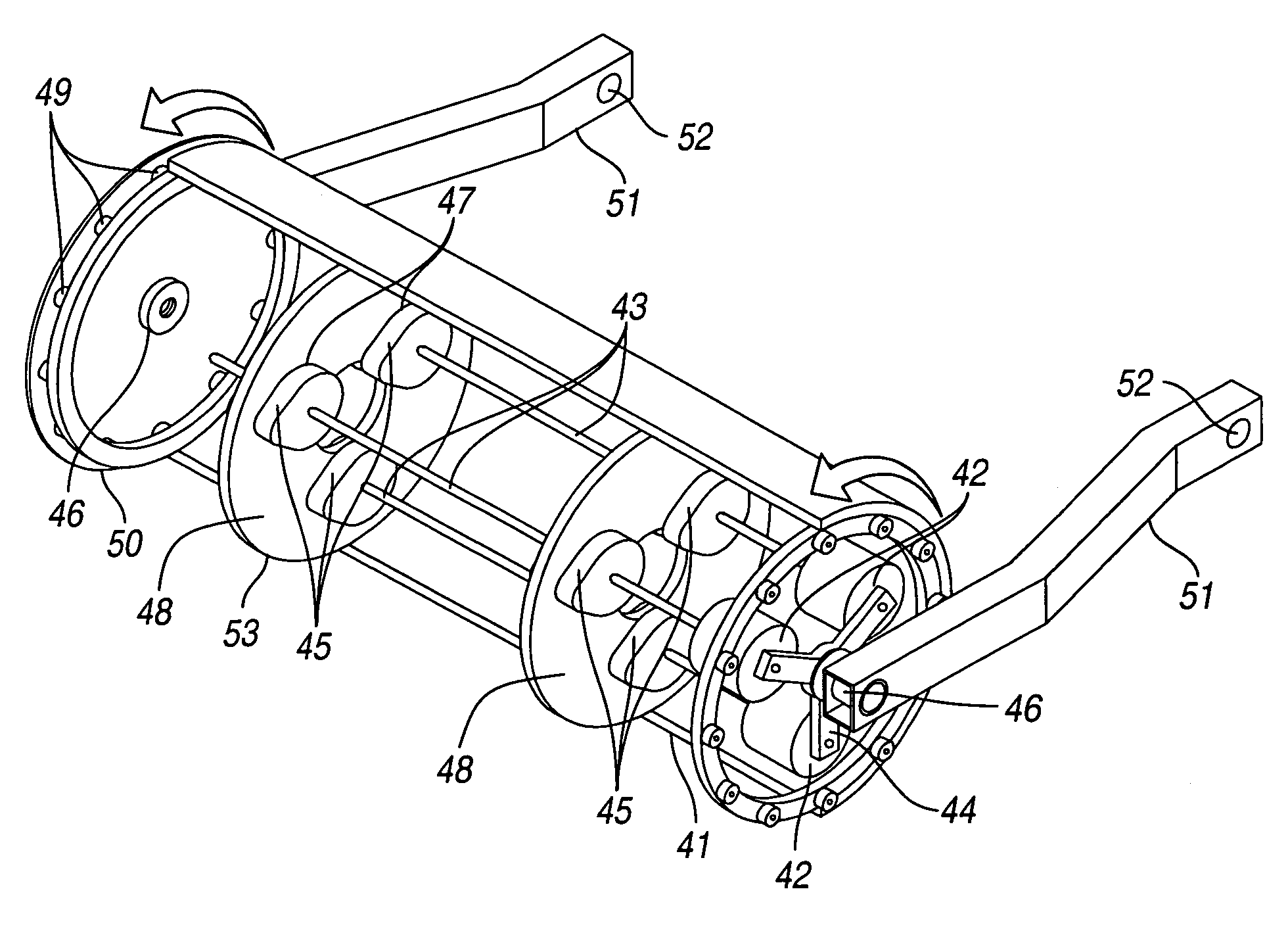
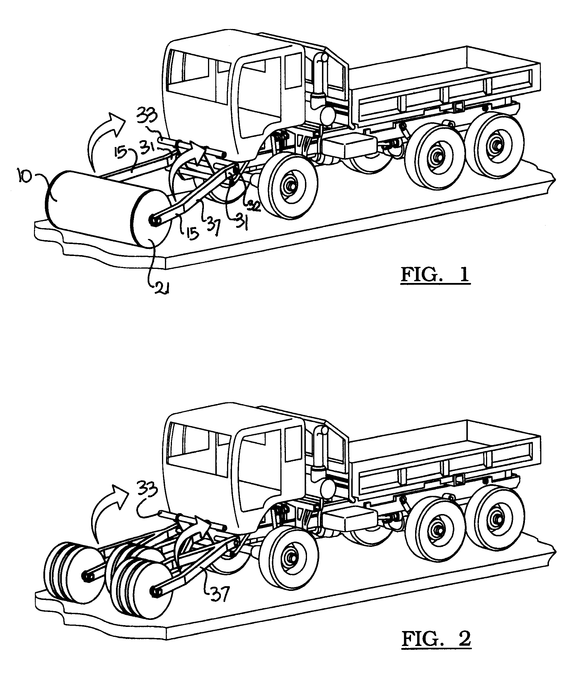
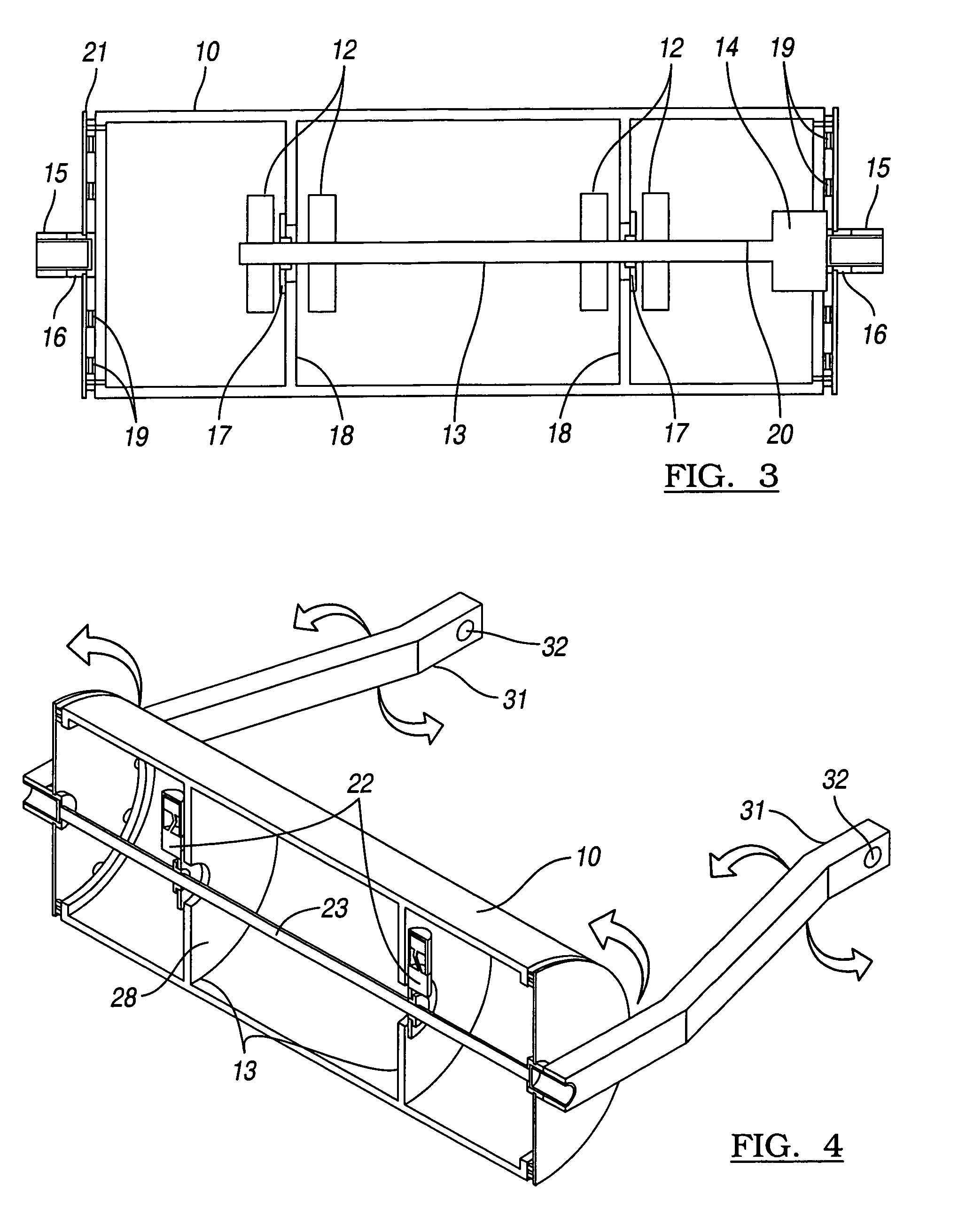
[0031]The invention includes a ground-contacting percussion system such as a drum (FIGS. 1-8) or a pad (FIGS. 9-10) that is mounted to the front of a wheeled or tracked vehicle or other propulsion means. Inside the ground-contacting percussion system is an internal, powered vibratory system that induces vibrations in the ground-contacting percussion system. Preferably, the vibratory system induces the vibrations along a non-vertical (inclined) axis. The ground-contacting percussion system (1) remains in substantial contact with the ground ahead of the propulsion means; and (2) transmits these vibrations, associated dynamic forces, and pressure waves ahead and through the ground to induce the detonation of land mines. The land mines will be detonated at a much greater distance than if a non-vibrating roller were used.

[0032]FIG. 1 shows the countermeasure system installed at the front of an FMTV 5-ton dump truck—one example of a “propulsion means”. The ground-contacting percussion sy...


PUM


Abstract

A vibratory countermine system and method associated with a propulsion means. The system is comprised of a ground-contacting percussion system assembly that is mounted to the front of the propulsion means. Also, a vibratory subassembly is mounted inside the ground-contacting percussion assembly for inducing vibrations in the ground. The ground-contacting percussion system is in contact with the ground ahead of the propulsion means. It transmits the vibrations, associated forces, and pressure waves below or ahead of the countermine system through the ground, thereby inducing the detonation of land mines.

Description

BACKGROUND OF THE INVENTION[0001]1. Field of the Invention[0002]This invention relates to a system and method for clearing mines using one or more ground-contacting percussion means that operate under the influence of a vibratory stimulus.[0003]2. Background Art[0004]One predominant method of mine-clearing relies on the M1 Abrams battle tank or a similar propulsion means. Such propulsion means can be equipped with a mine plow and mine roller attachments if needed. Other types of mine-clearing systems are either remote-controlled or manned. Mechanical mine-clearing systems are the most prevalent. They include various types, such as the flail, earth tillers, rollers, chains, pads, pedestals and plows—collectively termed herein as “ground-contacting percussion means”.[0005]A typical “flail” system has a rotating shaft that extends from the front of the mine-clearing propulsion means. The rotating shaft incorporates flexible members that radiate outwardly from the shaft to beat the grou...

Claims


Application Information

Patent Timeline
Patent Type & Authority Patents(United States)
IPC IPC(8): F41H11/16
CPCF41H11/18F41H11/30
Inventor SIMULA, GLEN RAYMONDTARNOWSKI, STEVEN JOHN
Owner GSE TECH
Why Eureka
Try Eureka