Oil pan useful for an internal combustion engine

a technology for internal combustion engines and oil pans, applied in the field of oil pans, can solve the problems of inability to rule out damage to the oil pans, the risk of ribs breaking, etc., and achieve the effect of improving protection against damag

Inactive Publication Date: 2009-01-27
MANN HUMMEL GMBH
View PDF36 Cites 10 Cited by
  • Summary
  • Abstract
  • Description
  • Claims
  • Application Information

AI Technical Summary

Benefits of technology

[0005]It is an object of the invention to provide an oil pan with improved protection against damage.
[0006]Another object of the invention is to provide an oil pan with damage protection using simple structural means.
[0009]The oil pan according to the invention has a protective shell which at least partly encloses the outer wall of the oil pan and is kept at a distance from the outer wall and in a fixed position relative thereto. The protective shell is a component manufactured separately from the outer wall but may be connected thereto and additionally protects the outer wall against mechanical damage. Because of the distance between the protective shell and the outer wall of the oil pan, it is ensured that any objects, such as stones, which penetrate or puncture the protective shell, for example, do not transmit the momentum directly to the outer wall and cannot damage the wall. Rather, the protective shell stops such objects before they can affect the wall.
[0010]The protective shell is advantageously held to the outer wall of the oil pan by means of spacer elements. These spacer elements ensure a uniform force distribution over the pan floor and the lateral walls. As a result, even point-like forces acting on the protective shell are uniformly distributed over a wide area across the outer wall of the oil pan via the spacer elements, so that the force peaks acting locally on the oil pan via the spacer elements are reduced.
[0011]The protective shell is preferably constructed as a closed wall without perforations. This has the advantage of offering an additional safeguard against oil leaks if the oil pan is damaged. If a leak were to occur in the outer wall of the oil pan, the escaping oil would be contained in the protective shell enclosing it. This reduces the risk of any contamination of the environment.

Problems solved by technology

This may cause problems if the engine is deposited at an angle, or if the ground is sloped or uneven, because some of the individual ribs are under substantially greater load than would be the case if the engine were placed evenly on the surface.
In this case there is a risk that the ribs will break.
If a stone strikes the oil pan, damage to the pan cannot be ruled out despite the protective ribs because of the high momentum transmitted and the locally limited introduction of the force.

Method used


Image

  • Oil pan useful for an internal combustion engine
  • Oil pan useful for an internal combustion engine
  • Oil pan useful for an internal combustion engine

Examples


Embodiment Construction

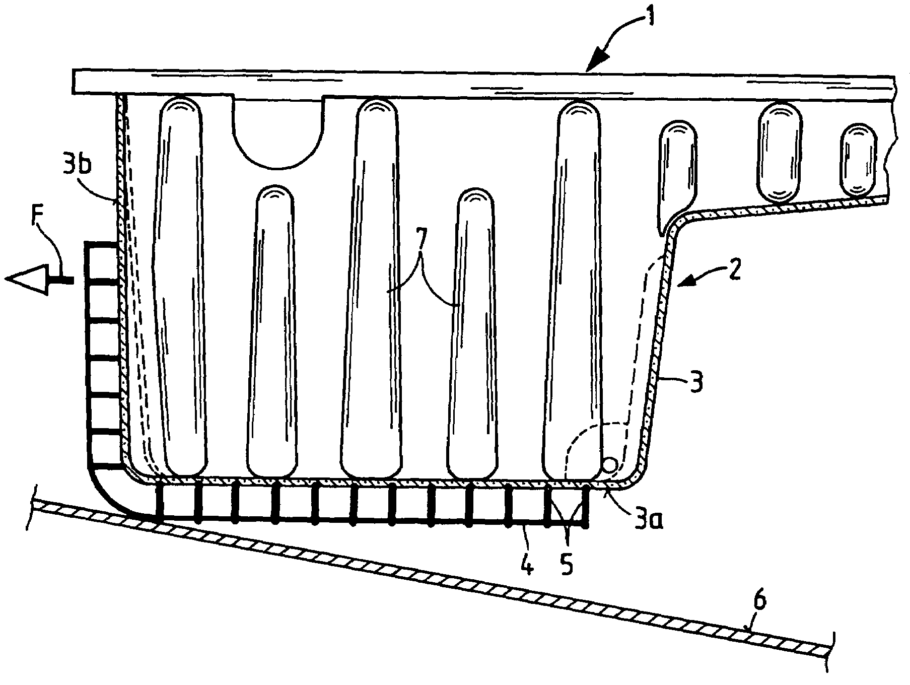
[0020]FIG. 1 shows an oil pan 1 for an internal combustion engine of a motor vehicle having an oil pan housing 2 made of a synthetic resin material (i.e., plastic). Preferably, the oil pan housing 2 is manufactured in an injection molding process. The outer wall 3 of the oil pan housing 2 comprises a pan floor 3a located at the bottom and circumferential sidewalls 3b. The pan floor 3a and the sidewalls 3b located toward the front of the vehicle in driving direction F are enclosed by a protective wall or shell 4, which is constructed as a separate component and is connected to the pan floor 3a and the front sidewall 3b by spacer elements 5. The spacer elements 5 ensure that the protective shell 4 is spaced apart from the outer wall 3 of the oil pan housing 2, such that a gap is formed between the outer wall 3 and the protective shell 4. The protective shell 4 is preferably also made of synthetic resin material, as are the spacer elements 5.

[0021]According to one preferred embodiment,...


PUM


Abstract

An oil pan, particularly for an internal combustion engine, having a protective contour member with a protective shell that is spaced apart from the outer wall of the oil pan. The protective shell at least partially encloses the outer wall of the oil pan and is held in a fixed position relative to the outer wall. The oil pan and the protective contour member are preferably made of a synthetic resin material. The protective contour member protects the oil pan against damage caused, for example, due to the impact of stones or if the oil pan comes into contact with an underlying uneven or sloped surface.

Description

BACKGROUND OF THE INVENTION[0001]The invention relates to an oil pan, particularly for an internal combustion engine, having a protective contour member disposed on an outer wall thereof.[0002]Oil pans for internal combustion engines, whose outer wall is provided with ribs for protecting the oil pan, particularly against strong mechanical impacts, e.g., caused by stones, are known in the art. An oil pan of this type is described, for example, in European patent application no. EP 1,041,253. The outside of the floor of the oil pan is provided with a plurality of spaced-apart ribs, a limited number of which have increased rigidity so that they are better able to absorb high mechanical forces.[0003]The oil pan, which is located on the underside of the engine, must carry the full weight of the engine, particularly as the engine is mounted in the vehicle or when it is placed on the ground after having been removed for maintenance. The weight forces of the engine are supported by the ribs...

Claims


Application Information

Patent Timeline
Patent Type & Authority Patents(United States)
IPC IPC(8): F02B77/00
CPCB60R19/00B60R13/0861F01M2011/0012F01M2011/002F01M2011/0091
Inventor JESSBERGER, THOMAS
Owner MANN HUMMEL GMBH
Why Eureka
Try Eureka