Systems and methods for detecting the presence and/or absence of a solid liquid or gas

a technology of solid liquid or gas detection and sensing system, applied in the direction of optical radiation measurement, instruments, using reradiation, etc., can solve the problems of long response time, subject to mechanical breakdown, and the channel itself is subject to corrosion and/or fouling with debris and/or mineral or chemical deposits, etc., to achieve the effect of increasing the system efficiency

Inactive Publication Date: 2009-01-27
GREENWALD TECH
View PDF7 Cites 51 Cited by
  • Summary
  • Abstract
  • Description
  • Claims
  • Application Information

AI Technical Summary

Benefits of technology

[0017]In accordance with the preferred exemplary embodiment, the RF energy emitter and RF energy detector structures are preferably located within a housing that is comprised of a conductive material, or which is shielded with conductive material for the purpose of limiting spurious emissions from the device. The shielded structure also limits extraneous RF noise thereby improving accuracy and the ability of the system to achieve finer resolution. Although any conductive housing is suitable for providing the shielding structure, in order to reduce manufacturing costs, it is preferred that the housing is embodied as a plastic structure having internal sidewalls coated with a material such as, for example, chrome. It should be recognized that other conductive materials will also be suitable and it is preferred that the thickness of the conductive shielding member be at least approximately a few skin depths at the primary RF emission frequency. Machined aluminum may also be used for the housing.
[0022]Currently in hospitals in about 50% of the cases the medical staff is using an infusion pump, even in situations where gravity infusion can be utilized. In these cases the medical staff is using infusion pump primarily to set the desired flow rate and to alarm the staff when there is no flow (for example; the patient is pinching the tube) or the infusion liquid bag is empty or out of product. The automated sensor systems and methods of the present invention can provide a simple device at a fraction of cost of an infusion pump that will provide the same desired functions.
[0026]A reduced cost which is only a fraction of an infusion pump;
[0029]Because they are small in size they can be mounted directly on the infusion pole and easily moved with the patient.
[0033]Yet another alternate embodiment of the present invention is directed to the medication packaging industry. In this industry, an optical sensor is currently the most common conventional solid product detector. The optical sensor is conventionally used to count and verify the number of dispensed medication units. During the packaging process dust is created which after a relatively short period causes the optical sensors to fail at an unaccepted rate as the dust builds up. This requires stopping the packaging process and cleaning the system periodically. The systems and methods of the present invention are not affected by the dust therefore it will allow running the packaging system for long periods without stopping and increasing the system efficiency.

Problems solved by technology

One problem associated with conventional sensing systems and methods which rely upon mechanical structures or floating bodies for determining fluid level is that they are subject to mechanical breakdown as a result of corrosion and / or fouling of the mechanical float structure with debris and / or mineral or chemical deposits.
In alternate approaches which rely upon a fluid level sensing channel, the channel itself is subject to corrosion and / or fouling with debris and / or mineral or chemical deposits.
This method has numerous disadvantages;The sensor must come into contact with the beverage concentrate liquid;It works only for systems where the concentrated liquid dispensing pump is powerful enough to create a vacuum, when the bag is out of product, and trigger the sensor.It has a long response time during which water is dispensed.
This method also has the disadvantage that it is necessary to have the two electrodes come in contact with the concentrated liquid and if the electrodes are not kept clean, the sensor will malfunction.
However, this technique will not work when the tubing through which the product travels is opaque, or when the liquid leaves residue on the inner walls of the tubing thereby blocking the sensor light.
Also, most of the Silicon or Tigon tubing that are used reflects or absorb most of the sensor infrared light and the sensitivity and resolution of devices which rely upon this technique is therefore very poor.
Furthermore, the performance of optical sensors can be degraded by the presence of debris, which is often encountered in packaging and manufacturing environments.
For example, in the pharmaceutical industry dust from the tablets can cause erroneous readings from optical sensing devices.
Accordingly, typical conventional mechanical, optical or electronic sensors for detecting the presence of a liquid in implementations for vending machines such as coffee dispensers and the like are inherently prone to degradation and breakdown and there remains a need for improvement or replacement of these conventional devices.
All of these known conventional mechanical systems for detecting the presence of a solid, liquid or gas are subject to degradation in performance over time as a result of the mechanical breakdowns noted above.
Accordingly, although this approach is not necessarily subject to the mechanical breakdown problems associated with conventional mechanical sensors for determining the presence of a solid liquid or gas, this alternate conventional technique has its own shortcomings and requires a significant economic expenditure for the manufacture of the ultrasonic detecting system.
Furthermore, ultrasonic detectors are not very suitable for use as a detection mechanism when there is an air gap between the product to be detected and the ultrasonic emitter.

Method used


Image

  • Systems and methods for detecting the presence and/or absence of a solid liquid or gas
  • Systems and methods for detecting the presence and/or absence of a solid liquid or gas
  • Systems and methods for detecting the presence and/or absence of a solid liquid or gas

Examples


Embodiment Construction

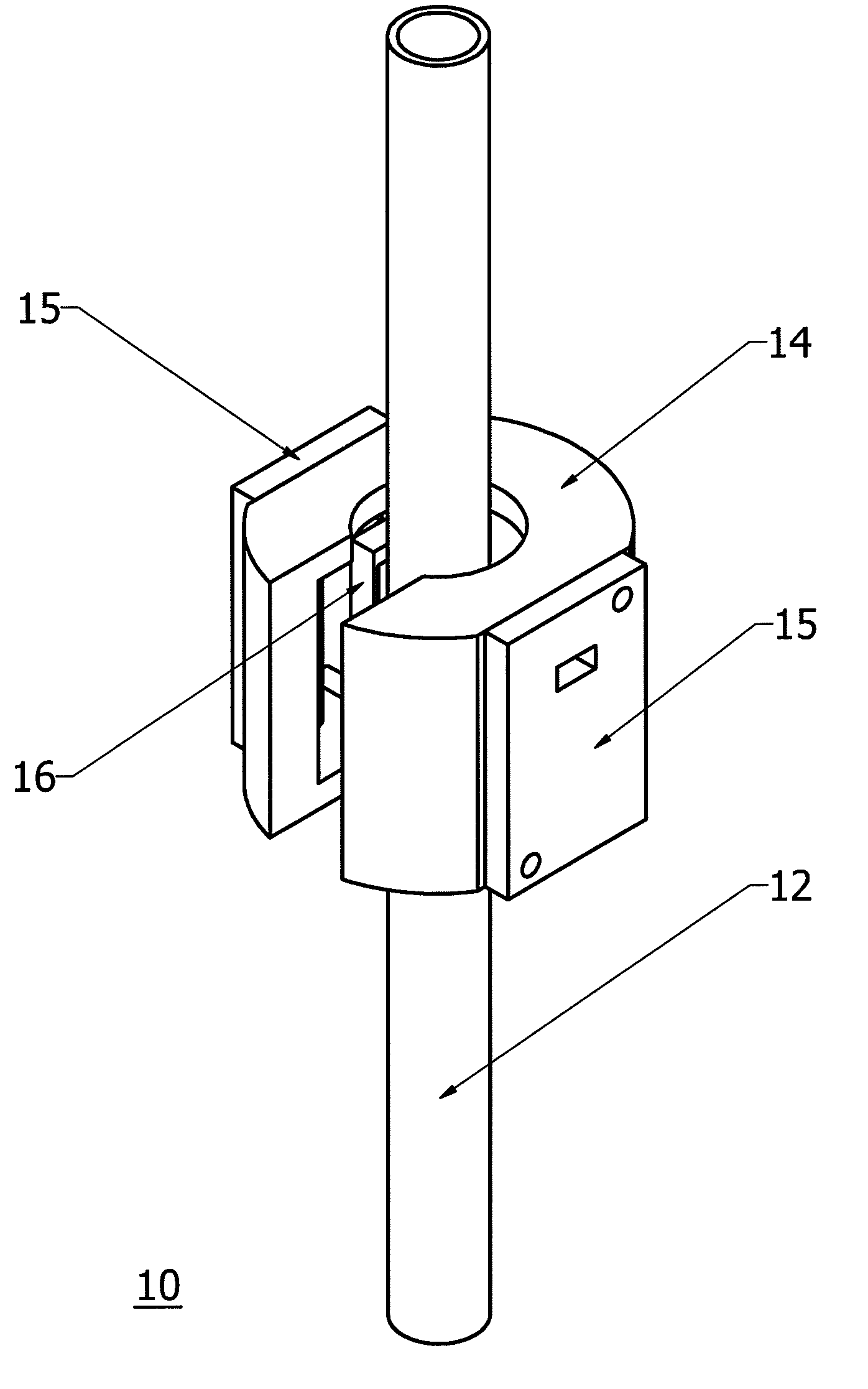
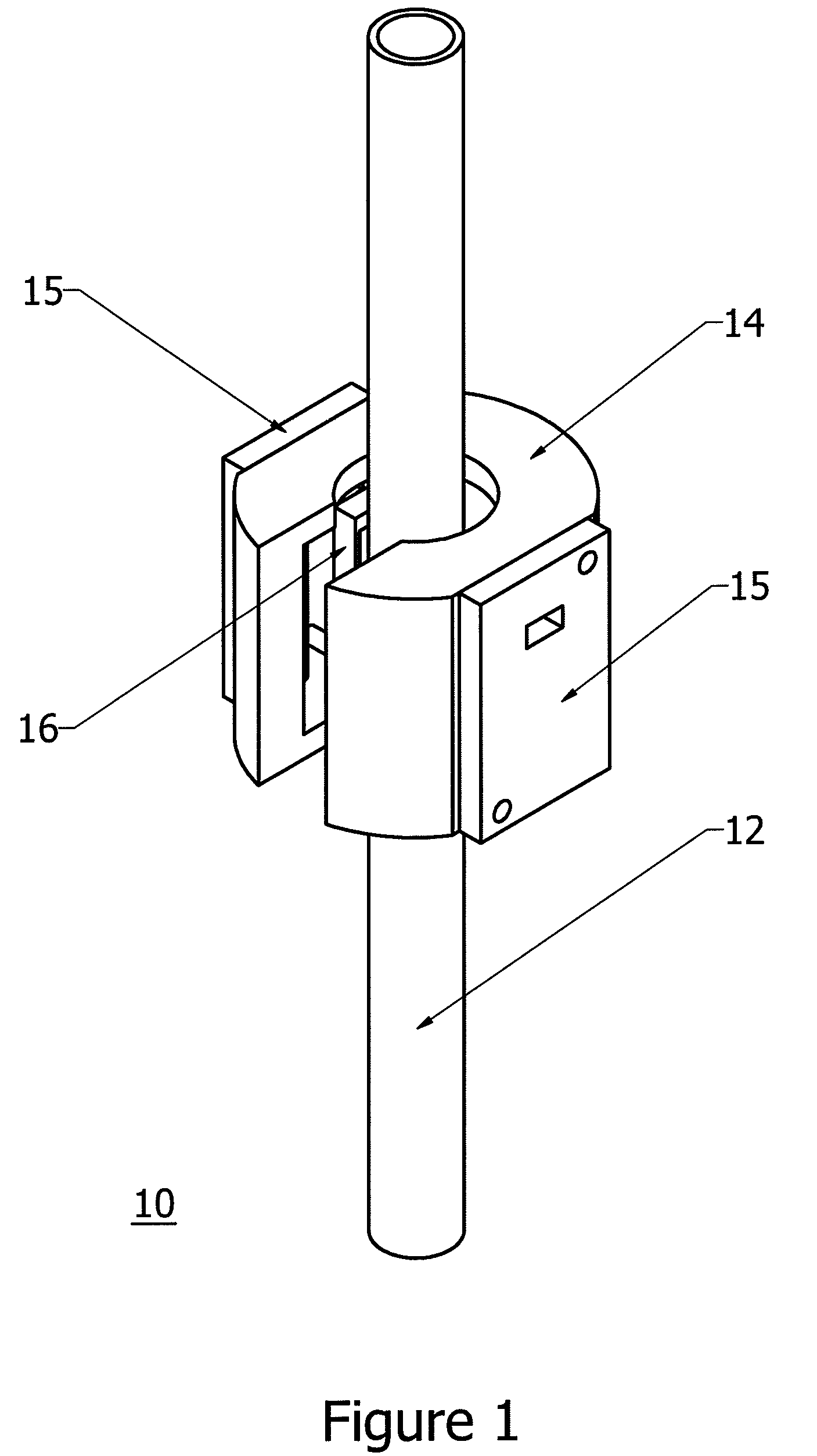
[0052]FIG. 1 illustrates a first preferred exemplary embodiment of the present invention, which is shown generally at 10. The arrangement illustrated in FIG. 1 is suitable for a wide variety of applications including fluid flow sensors, fluid level sensors, solid product detectors and pill counters. It should be recognized that these are just a few of the examples of applications for this arrangement. In this first preferred exemplary embodiment, a tube member 12, preferably comprised of a nonconductive material such as plastic, and the like, provides a transmission channel for a liquid, solid or gas.

[0053]An RF energy emitter / receiver structure housing 14 preferably surrounds or at least substantially surrounds the tube member 12. In illustration of FIG. 1, the housing 14 is a C-shaped generally cylindrical body located around the tube member 12. The RF energy emitter / receiver structure housing 14 may be comprised of a conductive material such as machined aluminum or any other cond...


PUM

PropertyMeasurementUnit
transmission frequenciesaaaaaaaaaa
frequenciesaaaaaaaaaa

Abstract

Systems and methods are described for detecting the presence and / or absence of a solid, liquid or gas which utilize an RF energy emitter and RF energy detector for determining whether a solid, liquid or gas is present within a defined physical space. More specifically, an RF energy emitter is provided at a first side of a solid, liquid or gas transmission channel and an RF energy receiver / detector is provided at an opposite side of the solid liquid or gas fluid channel. The RF energy emitter either continuously or periodically emits RF energy which in the preferred exemplary embodiment is in the high-frequency or more preferably ultrahigh frequency signal range. The amount of detected RF energy transferred across the channel is used in determining the presence and / or absence of a solid, liquid or gas.

Description

REFERENCE TO RELATED APPLICATIONS[0001]This application claims priority to U.S. Provisional Application No. 60 / 744,951, filed Apr. 17, 2006, entitled “Liquid / Air Bubble / Solid Objects Detector.” The benefit under 35 USC §119(e) of the United States provisional application is hereby claimed, and the aforementioned application is hereby incorporated herein by reference.BACKGROUND OF THE INVENTION[0002]1. Field of the Invention[0003]The present invention relates generally to the field of automated sensing systems and methods. More specifically, the present invention is directed to systems and methods for detecting the presence and / or absence of a solid, liquid or gas utilizing an RF energy emitter and RF energy detector for determining whether a solid, liquid or gas is present within a defined physical space between the RF energy emitter and RF energy detector.[0004]2. Description of the Related Art[0005]A wide variety of conventional systems and methods are available for determining wh...

Claims


Application Information

Patent Timeline
Patent Type & Authority Patents(United States)
IPC IPC(8): G01R27/32G01N27/00G01S13/08
CPCA61M1/3626A61M5/365A61M5/1689A61M2205/3317
Inventor GREENWALD, SHLOMOGREENWALD, ZIPORA
Owner GREENWALD TECH
Why Eureka
Try Eureka