
Capacitive power supply circuit and method

a capacitive power supply technology, applied in the direction of ac-dc conversion without reversal, power conversion systems, electrical equipment, etc., can solve the problems of electromagnetic compatibility, limited capacitive power supply circuits, and large losses, so as to avoid the use of mains filters

Active Publication Date: 2009-01-27
STMICROELECTRONICS SRL
View PDF16 Cites 10 Cited by
  • Summary
  • Abstract
  • Description
  • Claims
  • Application Information

AI Technical Summary

Benefits of technology

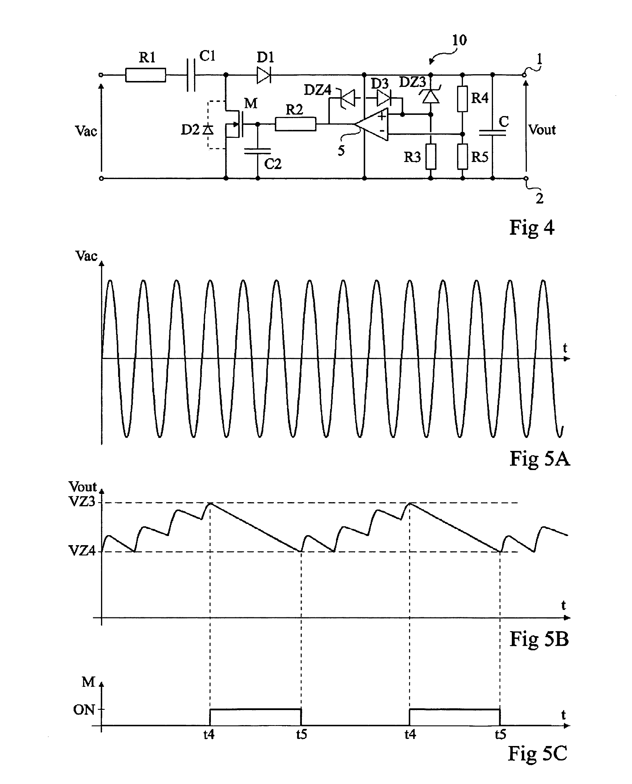
"The present invention provides a capacitive power supply circuit that generates no electromagnetic disturbance and avoids use of a mains filter. It also reduces stand-by losses and has a simple structure compared to magnetic transformer or high-frequency power supplies. The circuit includes a power storage element, at least one capacitor, and a controllable switch. The control means are formed of a hysteresis comparator or a comparator with a non-inverting input and a smaller second zener diode. The circuit can be integrated into an integrated circuit."

Problems solved by technology

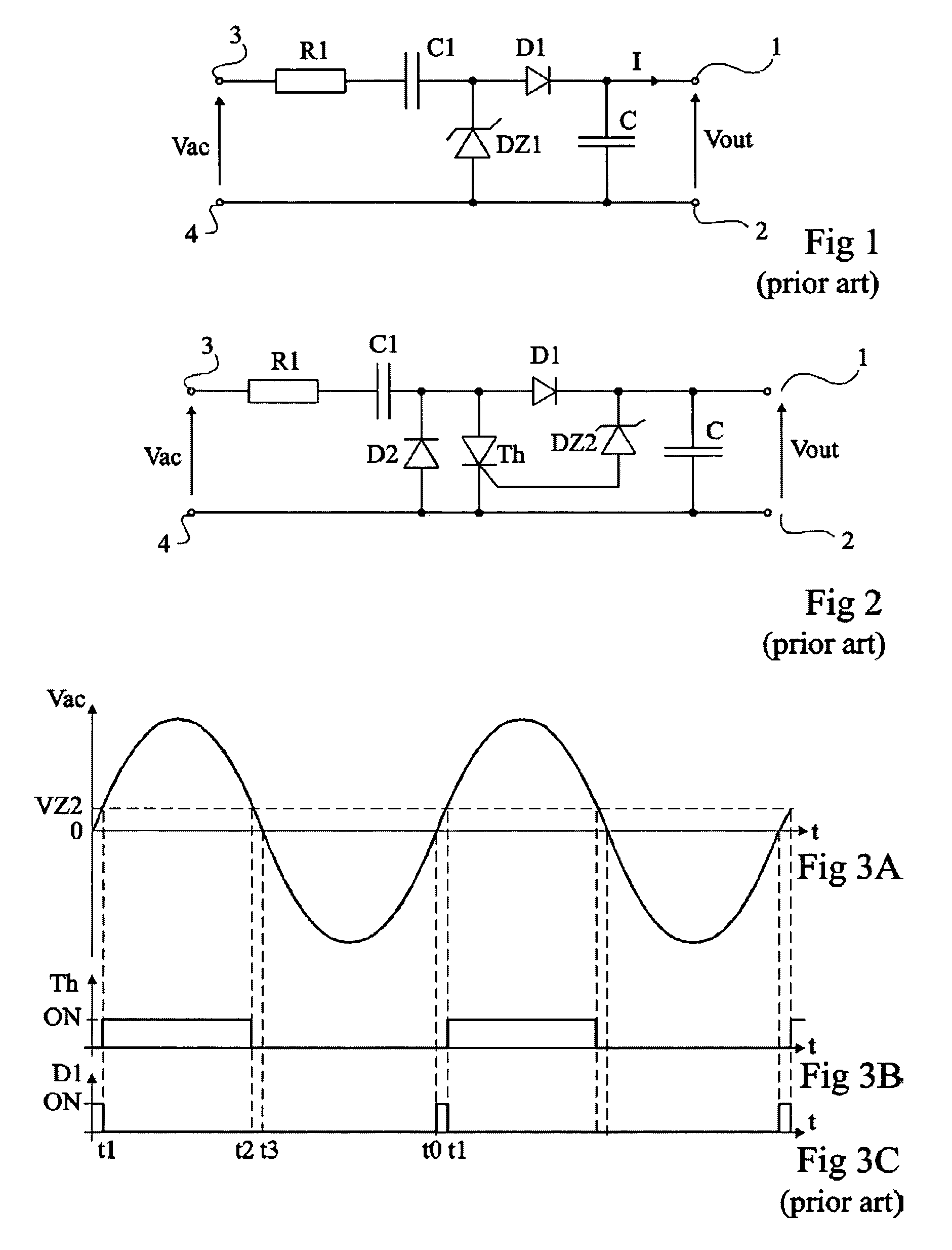
However, for output currents greater than some ten milliamperes, it generates significant losses when the system is at stand-by, that is, when no power is sampled by the load connected to terminals 1 and 2.
The significant losses during system stand-by result in that, in practice, the capacitive power supply circuits are limited to applications of supply of a current on the order of some ten milliamperes.
However, a disadvantage of the circuit of FIG. 3 is that it poses problems of electromagnetic compatibility and requires use of a mains filter (not shown) upstream of the system.

Method used


Image

  • Capacitive power supply circuit and method
  • Capacitive power supply circuit and method
  • Capacitive power supply circuit and method

Examples


Embodiment Construction

[0048]The following discussion is presented to enable a person skilled in the art to make and use the invention. Various modifications to the embodiments will be readily apparent to those skilled in the art, and the generic principles herein may be applied to other embodiments and applications without departing from the spirit and scope of the present invention. Thus, the present invention is not intended to be limited to the embodiments shown, but is to be accorded the widest scope consistent with the principles and features disclosed herein.

[0049]Same elements have been designated with same reference numerals in the different drawings. For clarity, only those elements which are necessary to the understanding of the present invention have been shown in the drawings and will be described hereafter. In particular, the A.C. power sources usable by a power supply circuit according to the present invention have not been detailed, said sources being compatible with any conventional A.C. ...


PUM


Abstract

A capacitive power supply circuit, comprising a power storage element between two output terminals for providing a rectified output voltage; in series between a first input terminal for applying an A.C. voltage and a first of the output terminals, at least one capacitor and a first diode; a switch controllable by application of a signal on a triggering terminal; and means for controlling said switch to the on state when the output voltage is in a predetermined range of values.

Description

PRIORITY CLAIM[0001]This application claims priority from French patent application No. 04 / 51836, filed Aug. 11, 2004, which is incorporated herein by reference.BACKGROUND OF THE INVENTION[0002]1. Field of the Invention[0003]Embodiments of the present invention relate to the field of capacitive power supply circuits which are intended to provide a rectified smoothed output voltage across a power storage element (capacitor) from an alternating current (A.C.) supply voltage.[0004]2. Discussion of the Related Art[0005]Capacitive power supply circuits belong to the different solutions for supplying power to a load from an A.C. supply voltage originating, for example, from the electric supply mains (220 volts or 110 volts).[0006]Capacitive power supplies are especially preferred to magnetic transformer or high frequency power supplies (switched-mode power supplies) for small powers (output currents of approximately some ten milliamperes) for reasons of cost or when the stand-by consumpti...

Claims


Application Information

Patent Timeline
Patent Type & Authority Patents(United States)
IPC IPC(8): H02M1/12H02M1/14H02M7/06H02M7/12
CPCH02M7/06H02M7/12H02M1/0085H02M7/05
Inventor BENABDELAZIZ, GHAFOURGONTHIER, LAURENT
Owner STMICROELECTRONICS SRL
Learn More