Determination of soil stiffness levels

a soil stiffness and level technology, applied in the field of soil stiffness level determination, can solve problems such as rapid increase in machine wear

Inactive Publication Date: 2009-01-27
AMMANN SCHWEIZ
View PDF16 Cites 30 Cited by
  • Summary
  • Abstract
  • Description
  • Claims
  • Application Information

AI Technical Summary

Benefits of technology

[0015]The object of the invention is to indicate a method and to provide an apparatus by means of which relative as well as absolute soil stiffness values can be determined quickly and in a simple manner over a soil surface.Solution
[0019]The determination according to the invention of relative values of the compacted soil or of the soil to be compacted is, according to the invention, an extremely fast process. This makes it possible to determine where the soil has already been compacted well and where it has been compacted less well. It is thus also possible to estimate whether the soil compaction can be increased further by passing over it again, or whether a soil compaction level that has already been achieved (achieved soil stiffness) can or cannot be increased significantly further with the available means.
[0042]A vibration plate will preferably be used as the vibration unit, since this is a low-cost product. However, it is also possible to use other machines, a trench roller and a single drum roller. However, the vibration plate has the advantage that the contact area with the soil surface is defined.
[0049]In addition, it should be noted that the occurrence of subharmonics can lead to machine damage if a soil compaction apparatus which has a soil contact unit is not appropriately designed. Damping elements are therefore installed between the respective soil contact unit and the rest of the machine parts in such a way that any transmission of subharmonics is damped. The entire soil compaction unit may, of course, be designed in such a way that low-frequency subharmonics do not cause any damage; their frequency is known on the basis of the statements in the detailed description. However, the amplitude of the excitation force can also be reduced to such an extent that the amplitudes of the subharmonics do not cause any damage, or are no longer present.

Problems solved by technology

In the German Laid-Open Specification DE-A 100 19 806, an attempt has been made to prevent “jumping” of a soil compaction apparatus (in particular in the case of a vibration plate) since this could result in loosening of already compacted soil and a rapid increase in machine wear.

Method used


Image

  • Determination of soil stiffness levels
  • Determination of soil stiffness levels
  • Determination of soil stiffness levels

Examples


Embodiment Construction

Object

[0015]The object of the invention is to indicate a method and to provide an apparatus by means of which relative as well as absolute soil stiffness values can be determined quickly and in a simple manner over a soil surface.

Solution

[0016]The object was achieved with regard to the method by the features of patent claim 1, and with regard to the apparatus by the features of patent claim 8.

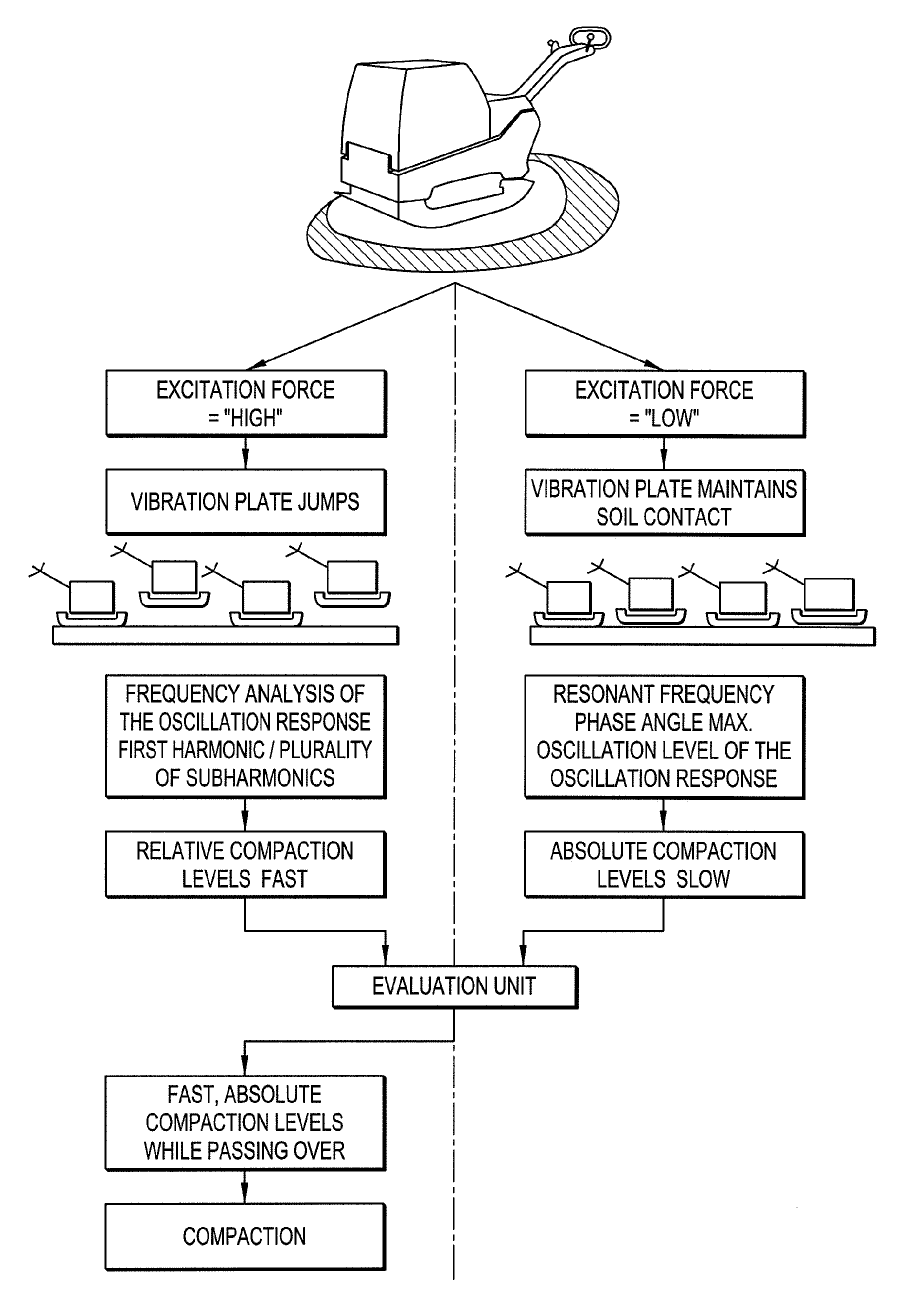
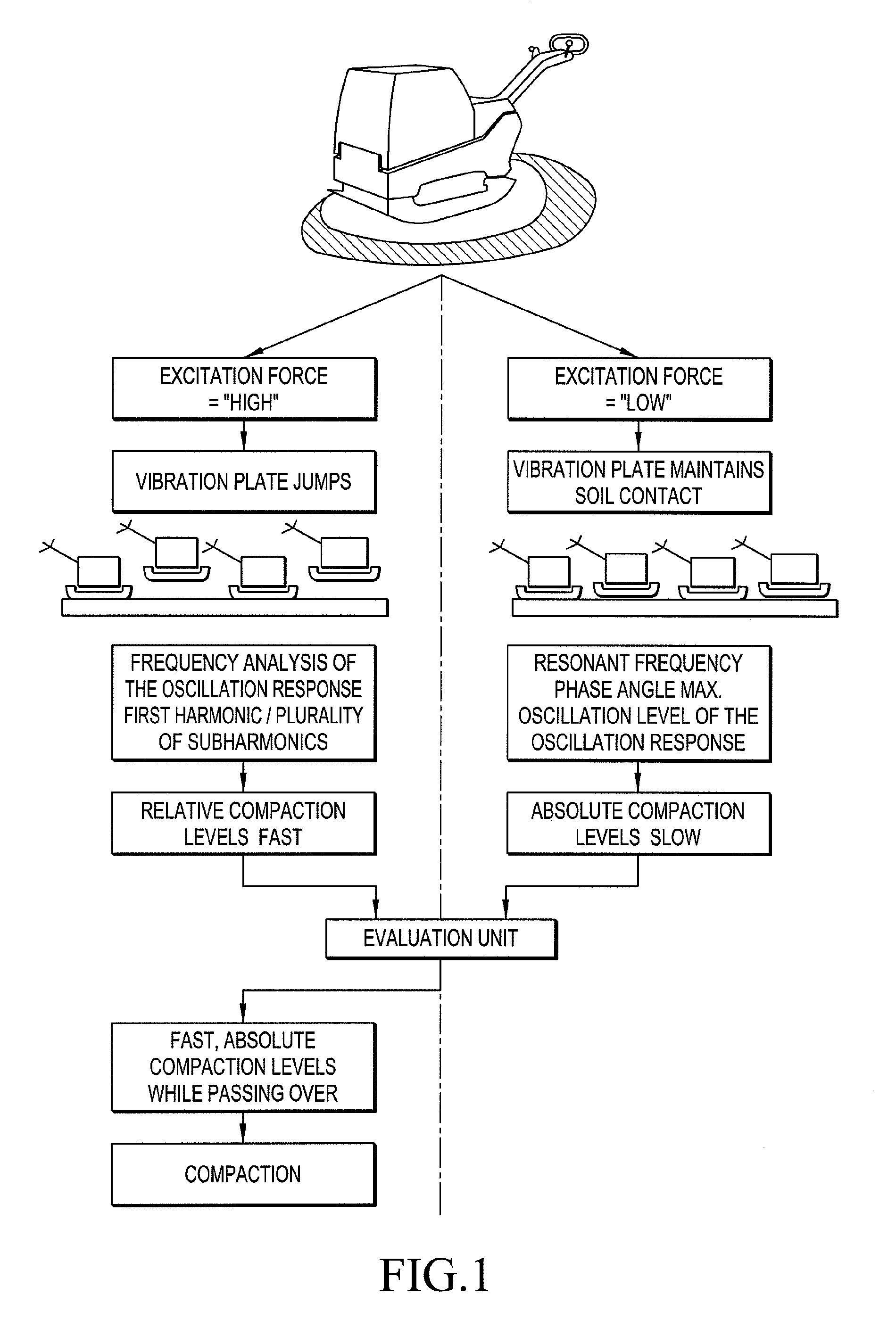
[0017]The essence of the invention, as can be seen from FIG. 1, is the use of only a single machine (apparatus) for absolute measurements and relative measurements of soil compaction levels and for soil compaction. The absolute measurements require a certain amount of time in order to set resonance of an oscillating system, formed from the vibration unit and the soil area on which the vibration unit is in continuous contact with the soil surface. The determination of relative values is a fast method; the values are obtained directly while passing over the soil surface. If this machine is calibr...


PUM


Abstract

According to the invention, a single device permits the relative soil rigidity values of a section of soil to be determined in a rapid measuring method and in addition, absolute soil rigidity values to be determined in a slightly slower method. If the device is calibrated with the aid of the measured absolute values, a rapid absolute measurement can also take place. The device can also be used for soil compaction.

Description

[0001]This application is the national phase under 35 U.S.C. § 371 of the PCT International Application No. PCT / CH04 / 00592, which has an international filing date of Sep. 20, 2004, and which claims priority under 35 U.S.C. § 119(a)-(d) of European Patent Office Application 0345688.7, filed Sep. 19, 2003.TECHNICAL FIELD[0002]The invention relates to a method and an apparatus for determination of soil stiffness levels, in which case this apparatus can also be used for soil compaction.[0003]Particularly in civil engineering, there is a desire on the one hand to know before the work starts what the soil conditions are with respect to soil compaction to be carried out later; what soil compaction levels can be achieved; whether soil areas must be removed and possibly new material should be deposited, in order to achieve a predetermined soil compaction or predetermined load-bearing capability for road, railroad, airport runway construction, etc, at all.[0004]On the other hand, when soil co...

Claims


Application Information

Patent Timeline
Patent Type & Authority Patents(United States)
IPC IPC(8): G01V3/00E01C19/38E01C19/28E02D3/046
CPCE01C19/288E02D3/046
Inventor ANDEREGG, ROLANDVON FELTEN, DOMINIK
Owner AMMANN SCHWEIZ
Why Eureka
Try Eureka