Straight edge clamping device

a clamping device and straight edge technology, applied in the direction of manufacturing tools, writing aids, circular curve drawing instruments, etc., can solve the problems of increasing the ultimate manufacturing cost of the straight edge clamp beyond practicality, affecting the extrusion cost and ultimately the cost of the straight edge, and inherent in the nature of aluminum extrusion, so as to achieve the effect of less material and improved stability of the position

Active Publication Date: 2009-02-03
EMERSON EUGENE
View PDF26 Cites 14 Cited by
  • Summary
  • Abstract
  • Description
  • Claims
  • Application Information

AI Technical Summary

Benefits of technology

[0010]The present invention is contrived to overcome the conventional disadvantages. Therefore, an object of the invention is to provide an extrusion cross-section for a straight edge clamp having improved stability of its position while the clamp is engaged while using less material.
[0011]Another object of the invention is to provide an extrusion cross-section for a straight edge clamp that enables a power tool to cut a workpiece more accurately when the workpiece is secured by the clamp.
[0019]To provide structural rigidity and firm interlocking effects, in the general shape of the cross section, the second predetermined interval is larger than the first predetermined interval, the third predetermined interval is larger than the second predetermined interval, the fourth predetermined interval is larger than the third predetermined interval, and the fifth predetermined interval is larger than the fourth predetermined interval.
[0028]The advantages of the present invention are: (1) the straight edge clamp is kept stable after the workpieces are clamped and during wood working on the workpieces using the extrusion cross-section fro the device due to the shape of the unique cross-section that keeps the base rigid even with reduced cross-sectional area; (2) Woodworking accuracy of the finished product improves; and (3) the improved straight edge clamp can be manufactured with reduced the manufacturing cost appreciably because of the effective extrusion cross-section of the invention.

Problems solved by technology

The problem in a straight edge clamp by prior art is that aluminum extrusion products used for making straight edges has a minimum dimension variation of 20 mil, and this variation is the potential amount of movement of the straight edge even when the bar clamp of the straight edge clamp is securely engaged.
The problem is inherent in the nature of aluminum extrusion.
Such factors also affect the cost of the extrusion and ultimately the cost of the straight edge.
However, it increases the ultimate manufacturing cost of the straight edge clamp beyond practicality.

Method used


Image

  • Straight edge clamping device
  • Straight edge clamping device
  • Straight edge clamping device

Examples


Embodiment Construction

[0034]The U.S. Pat. No. 6,622,997 of the applicant is incorporated by reference into this disclosure as if fully set fourth herein.

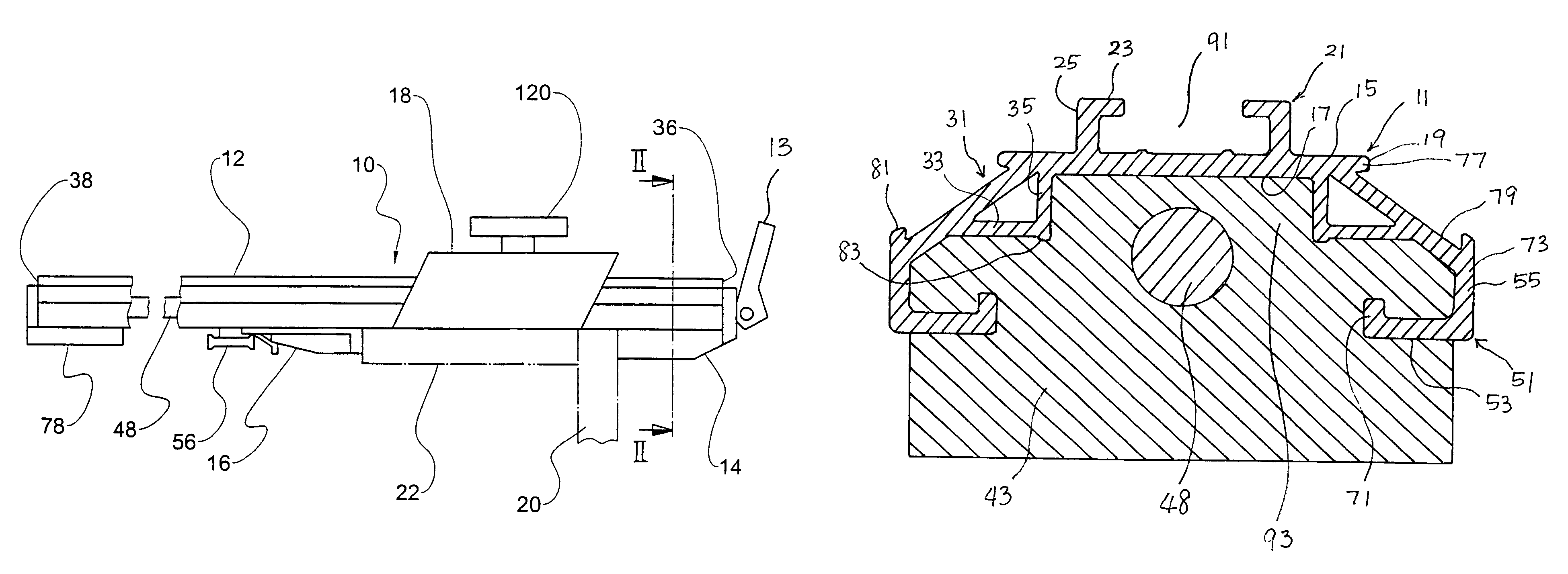
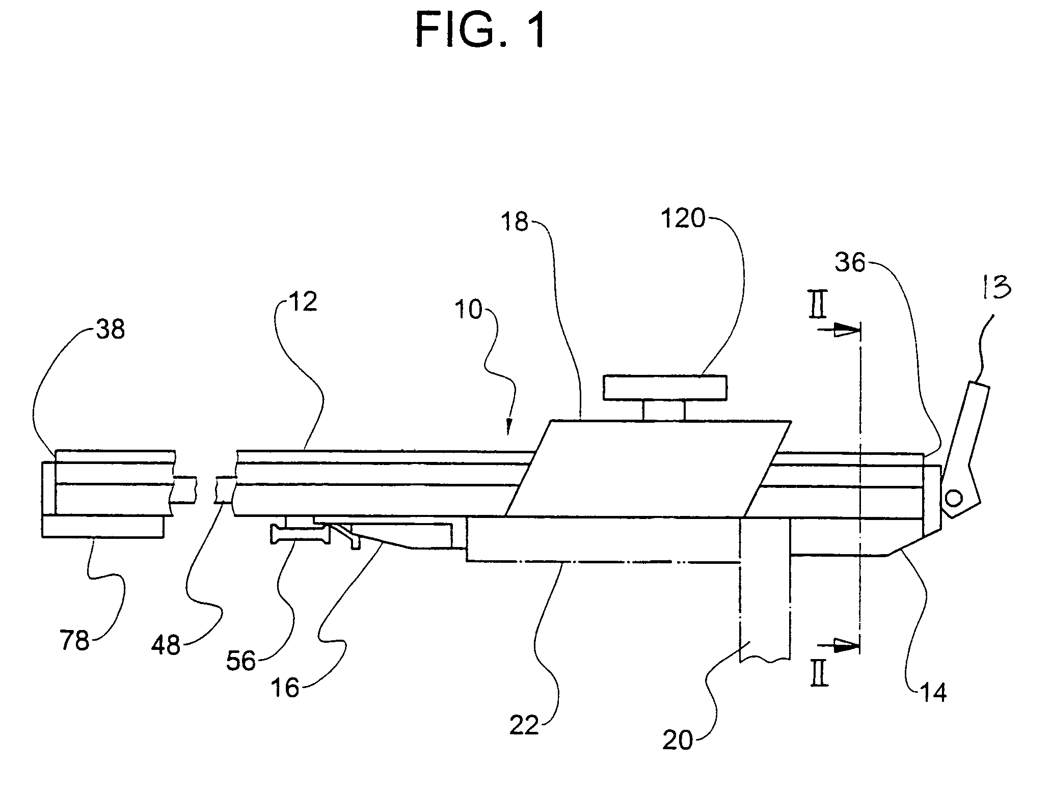
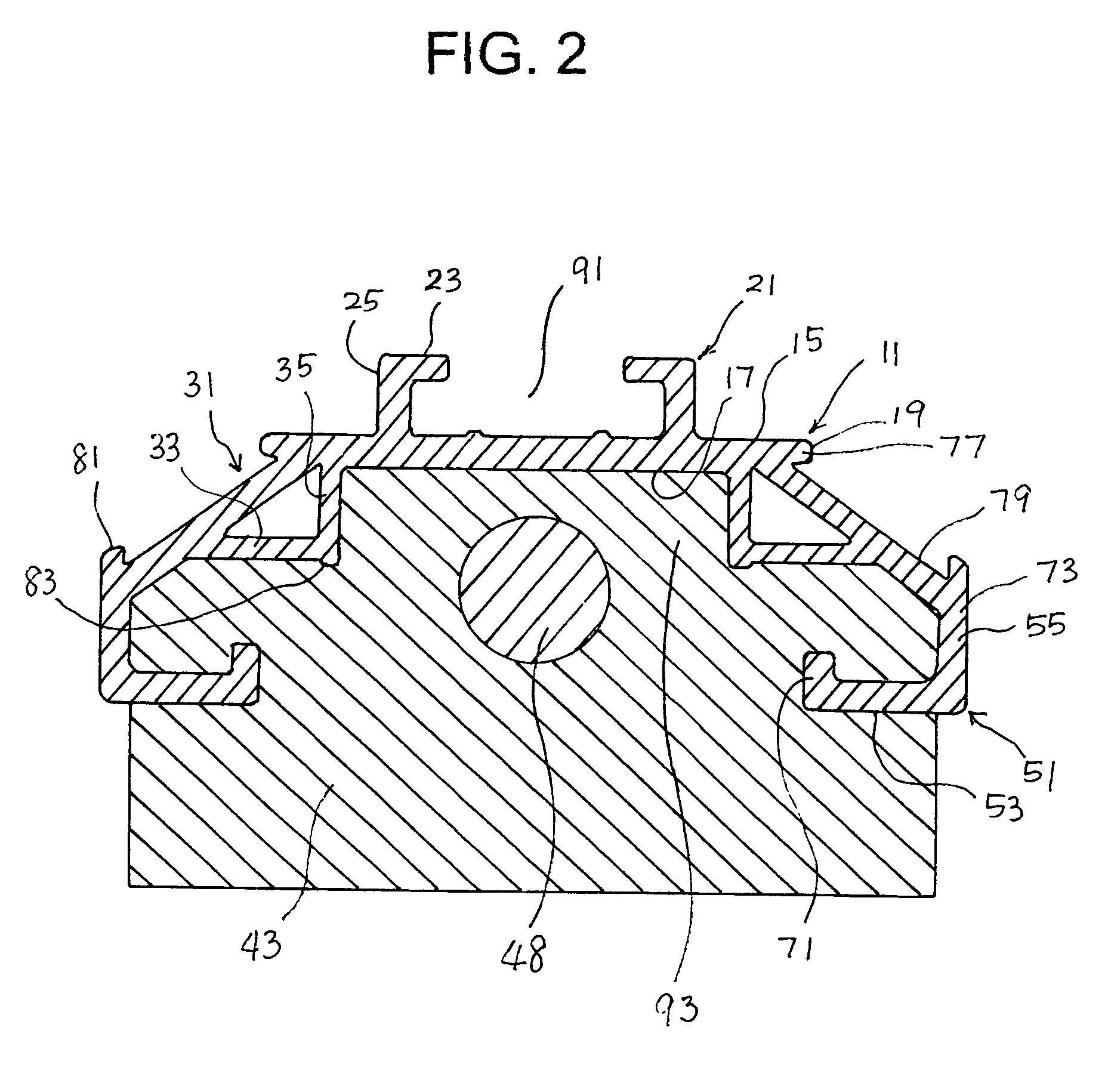
[0035]FIG. 1 schematically shows a straight edge clamping device 10 for woodworking. FIGS. 2 and 3 show a cross-section of the straight edge clamping device 10.

[0036]For the straight edge clamping device 10, an extrusion cross-section is provided for the straight edge clamping device 10 that has an elongated hollow base 12, first and second stops 14, 16, and a clamp 13. The elongated hollow base 12 has a constant cross-section. The first stop 14 is fixed at an end of the base 12 and the second stop 16 is movably provided along the base 12. The clamp 13 is for holding the workpieces 20, 22 together.

[0037]As shown in FIGS. 2 and 3, the extrusion cross-section of the base 12 includes a flat base portion 11, two L-cross-sectioned portions 21, two hollow portions 31, and two flanges 51.

[0038]The flat base portion 11 has a top surface 15, a bottom surface 17, ...


PUM


Abstract

An extrusion cross-section for a straight edge clamping device including (a) an elongated hollow base having a constant cross-section; (b) a first stop fixed at one end of the base; (c) a second stop movably provided along the base; and (d) a clamp for holding the workpieces together, includes a) a flat base portion having top and bottom surfaces, and two edges; b) two L-cross-sectioned portions having horizontal and vertical parts, facing each other, integrated with the flat base on the top surface of the flat base forming a top groove; c) two hollow portions, facing each other, integrated with the flat base on the bottom surface of the flat base forming a bottom groove; and d) two flanges having a horizontal part, vertical parts, facing each other, integrally connected to the corresponding hollow portion, wherein the cross-section has a right-left symmetry with a vertical center line as symmetry axis.

Description

BACKGROUND OF THE INVENTION[0001]The present invention relates to an extrusion cross-section for a straight edge clamping device. More particularly, the invention relates to an extrusion cross-section for a straight edge clamping device used to secure workpieces and to guide a power tool along the straight edge. Also, the invention relates to an extrusion cross-section for a straight edge clamping device which is strong and robust to external mechanical strain.[0002]Straight edge clamps are used in wood working for having a straight edge secured to a workpiece or workpieces so that a power tool or a guide for a power tool can be moved along the straight edge, for example, to form a cut edge with a circular hand saw or to form a trimmed edge with a hand router. Also, straight edge clamps are used for the purpose of holding accessory tool against a workpiece, for example, to form pocket holes.[0003]A straight edge clamp by prior art includes a straight edge that is made of extruded al...

Claims


Application Information

Patent Timeline
Patent Type & Authority Patents(United States)
IPC IPC(8): B43L7/00
CPCB25B1/2489
Inventor EMERSON, EUGENE
Owner EMERSON EUGENE
Why Eureka
Try Eureka