Application of loading ledges

a technology of loading ledges and ledges, which is applied in the direction of bundling articles, stacking articles, and bundling machine details, etc., can solve the problems of short working cycle, inability to produce a small number of unit loads consisting of one or more packages, and often has to be refilled on pallet piles, etc., to achieve simplified maintenance of inventive application systems and applications, enhanced loading ledges, and easy updating

Inactive Publication Date: 2009-02-03
INTER IKEA SYST
View PDF19 Cites 13 Cited by
  • Summary
  • Abstract
  • Description
  • Claims
  • Application Information

AI Technical Summary

Benefits of technology

[0011]One object of the present invention is to simplify the application of loading ledges on unit loads by means of an application machine and method utilising the application machine according to the invention.
[0014]By using a system, an application machine and method according to the invention, the following advantages are obtained. The required storage area is minimised, the transport and application of pallets, in this case, loading ledges is enhanced by being more flexible and simplified. Old application systems are easily updated due to the module thinking when inventing this new system according to the present invention. Furthermore, the maintenance of the inventive application system and application machine is simplified. Moreover, the feeding and application of loading ledges on the units loads are more reliable in comparison to wooden pallets. The recycling of loading ledges is also enhanced and simplified, compared to recycling of pallets. All of these advantages reduce the costs for manufacture, storing, feeding, application, transport, and recycling of the loading ledges.

Problems solved by technology

One disadvantage for these application systems or machines is that they have a short working cycle.
This means that these systems only can produce a small number of unit loads consisting of one or more packages because the stock of pallets in the system is small.
Consequently, the pallet pile often has to be refilled with new pallets requiring more manual work.
Alternatively, the size of the required space for the application systems increases if the pallet stock is enlarged, especially when wooden pallets are being used.
Another disadvantage, when wooden pallets are used, is that the feeding of the pallets from the storage onto the transport path is easily interrupted if pallets are stuck, jammed or hook together because of damaged pallets.
The pallets can have damages in the form of nails or wood pieces sticking out, broken wood with pieces missing or wood pieces that are not holding together properly.
Moreover, two or more wooden pallets may stick together due to too rough wooden surfaces creating a too high friction.
A problem is that the wooden pallets have fixed standard sizes.
This means that packages having a size not corresponding to the size of the wooden pallets make it difficult to optimise the filling grade of the truck or train.
Furthermore, empty wooden pallets are heavy and occupy a large volume, whereby a lot of “air” and weight are transported together with empty wooden pallets, whereby the number of transports increase.
Another problem when packages are to be applied on wooden pallets is that packages, which have a width not corresponding to the width of the wooden pallets, have to be positioned symmetrically on the wooden pallets.
Moreover, wooden pallets are difficult to recycle due to the mixture of different materials, i.e. wood and metal nails that have to be separated during recycling.
This give rise to new problems involving the design of other means for storing, feeding, applying, and transporting both loading ledges and associated unit loads.

Method used


Image

  • Application of loading ledges
  • Application of loading ledges
  • Application of loading ledges

Examples


Embodiment Construction

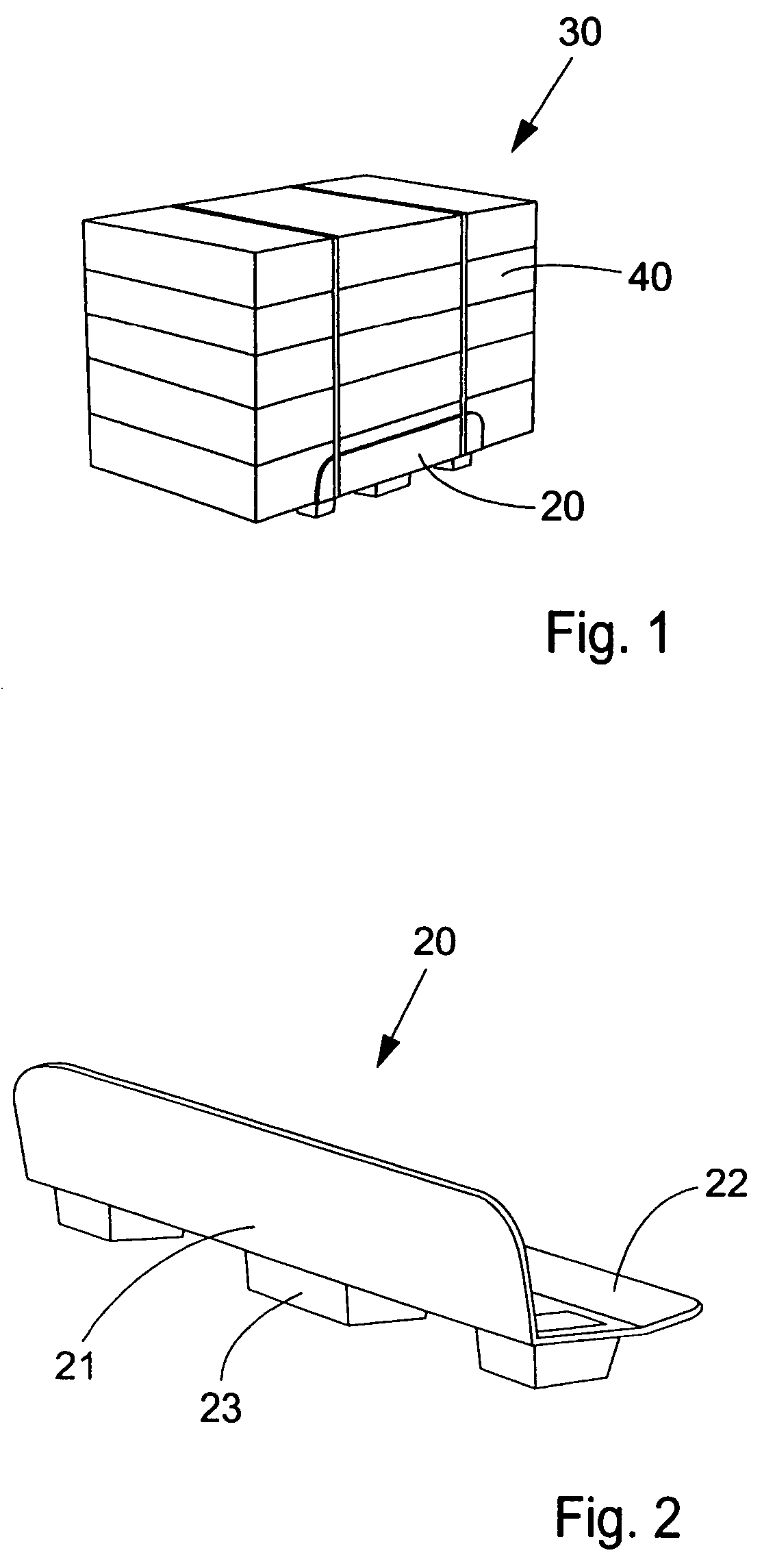
[0027]FIG. 1 shows a unit load 30 comprising at least one package 40. One of two loading ledges 20 is positioned at one bottom edge of the unit load and attached to the unit load by straps. The other loading ledge (not shown) is positioned and in contact with the opposite bottom edge of the unit load.

[0028]FIG. 2 shows the loading ledge 20 in more detail. The loading ledge comprises one vertical flange 21, one horizontal flange 22, and at least one support 23 in the form of a foot. The support is hollow so that another loading ledge (not shown) may be stacked on the shown loading ledge.

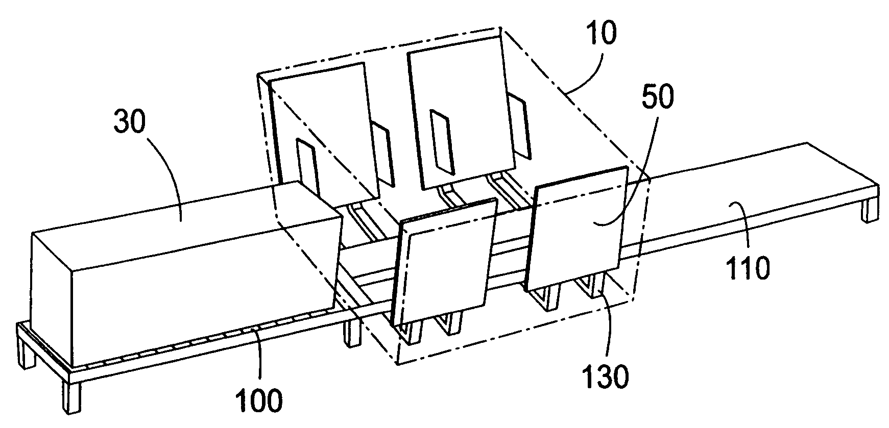
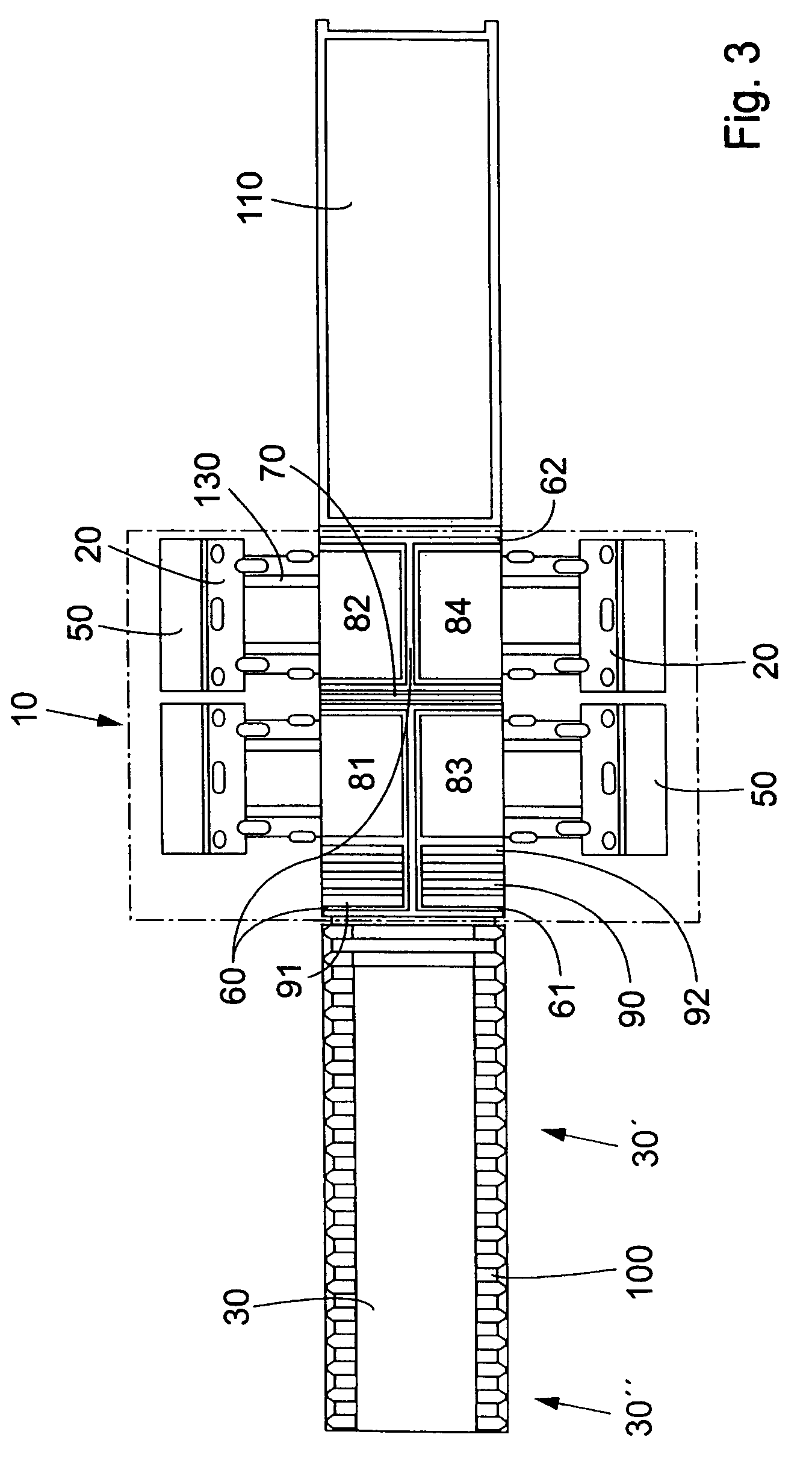
[0029]FIG. 3 shows a machine 10 for application of loading ledges 20 onto the unit load 30 comprising the at least one package 40. Each package, preferably of corrugated board, cardboard, paper, or any suitable package material may contain any kind of product / s for further transport or storage.

[0030]Each package 40 can be large, e.g. large enough to create the unit load 30 consisting of only one packa...


PUM

PropertyMeasurementUnit
angleaaaaaaaaaa
angleaaaaaaaaaa
angleaaaaaaaaaa

Abstract

A system for applying loading ledges onto a unit load positioned on supporting means. The system comprises an application machine. The system also comprises means for separating the unit load from the supporting means in the vertical direction. The system also comprises means for applying one or more loading ledges to two or more opposite, lower edges of the unit load when separated from the supporting means.

Description

[0001]This application is a 371 national stage of PCT / SE03 / 00635 filed Apr. 22, 2003.TECHNICAL FIELD[0002]The present invention relates to a system for applying loading ledges onto a unit load positioned on supporting means. The system comprises an application machine. Moreover, the present invention relates to a method for applying the loading ledges by using the system.DESCRIPTION OF PRIOR ART[0003]Systems according to the prior art for applying packages on for example pallets often use a stock of pallets, e.g. wooden pallets, in communication with means for transporting each pallet on a path into a package loading area. In the package loading area, each package, if it is a large package, or several packages, if they are small, is / are loaded onto its pallet forming a unit load. The unit load is then transported, e.g. to a strapping or wrapping area, where the package / s is / are secured to the pallet for further transport or handling.[0004]One disadvantage for these application syste...

Claims


Application Information

Patent Timeline
Patent Type & Authority Patents(United States)
IPC IPC(8): B65B61/00B65B13/18B65D19/40B65B27/00B65B59/00B65D71/00B65D71/02B65D71/72B65G57/00
CPCB65B13/181B65D71/0092B65D71/02
Inventor DICKNER, ALLAN
Owner INTER IKEA SYST
Why Eureka
Try Eureka