Cloth holding device

a technology of holding device and cloth, which is applied in the direction of embroidering machine, automatic machine, textiles and paper, etc., can solve the problems of difficult for the user to properly position the separate set of magnets, difficult for the user to readily and reliably rearrange the holding and difficulty in partially releasing the hold of the workpiece cloth by the outer frame, etc., to achieve the desired position easily and reliably, the effect of simplifying the attachment of the attachment uni

Inactive Publication Date: 2009-02-03
BROTHER KOGYO KK
View PDF21 Cites 13 Cited by
  • Summary
  • Abstract
  • Description
  • Claims
  • Application Information

AI Technical Summary

Benefits of technology

[0012]According to the cloth holding device of the present invention, since the presser frame is pressed against the support frame by attaching an attachment unit to the presser frame after clamping the workpiece cloth between the support frame and the presser frame, the workpiece cloth can be held firmly between the support frame and the presser frame. Also, since the attachment unit is positioned by the positioning unit, the attachment of the attachment unit to the presser frame is simplified. Also, even after the workpiece cloth is held by the support frame, presser frame, and attachment unit, the workpiece cloth can be stretched and be positioned readily and reliably to the desired position by removing and thereafter reattaching a part of the attachment unit in a step-by-step manner.
[0013]Also, in the case where the attachment unit is arranged to be switchable from the detached position to the attached position by the switch unit, the attachment unit is consistently mounted to the presser frame, thereby preventing the attachment unit from being lost.

Problems solved by technology

Furthermore, it is difficult to partially release the hold of the workpiece cloth by the outer frame and the inner frame after the workpiece cloth is clamped by the outer frame and the inner frame being fitted with each other.
Thus, it is difficult for the user to readily and reliably rearrange the hold of the workpiece cloth by displacing the workpiece cloth in desired amounts relative to the embroidery frame and at the same time stretching the workpiece cloth in order to position the workpiece cloth in the desired position with respect to the embroidery frame.
Therefore, it is difficult for the user to properly position the separate set of magnets to the position of the magnets provided in the outer frame.

Method used


Image

  • Cloth holding device
  • Cloth holding device
  • Cloth holding device

Examples


first embodiment

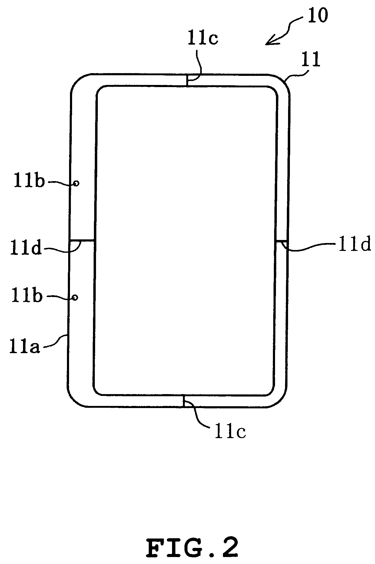
[0049]FIGS. 1 to 7 indicate the first embodiment of the present invention.

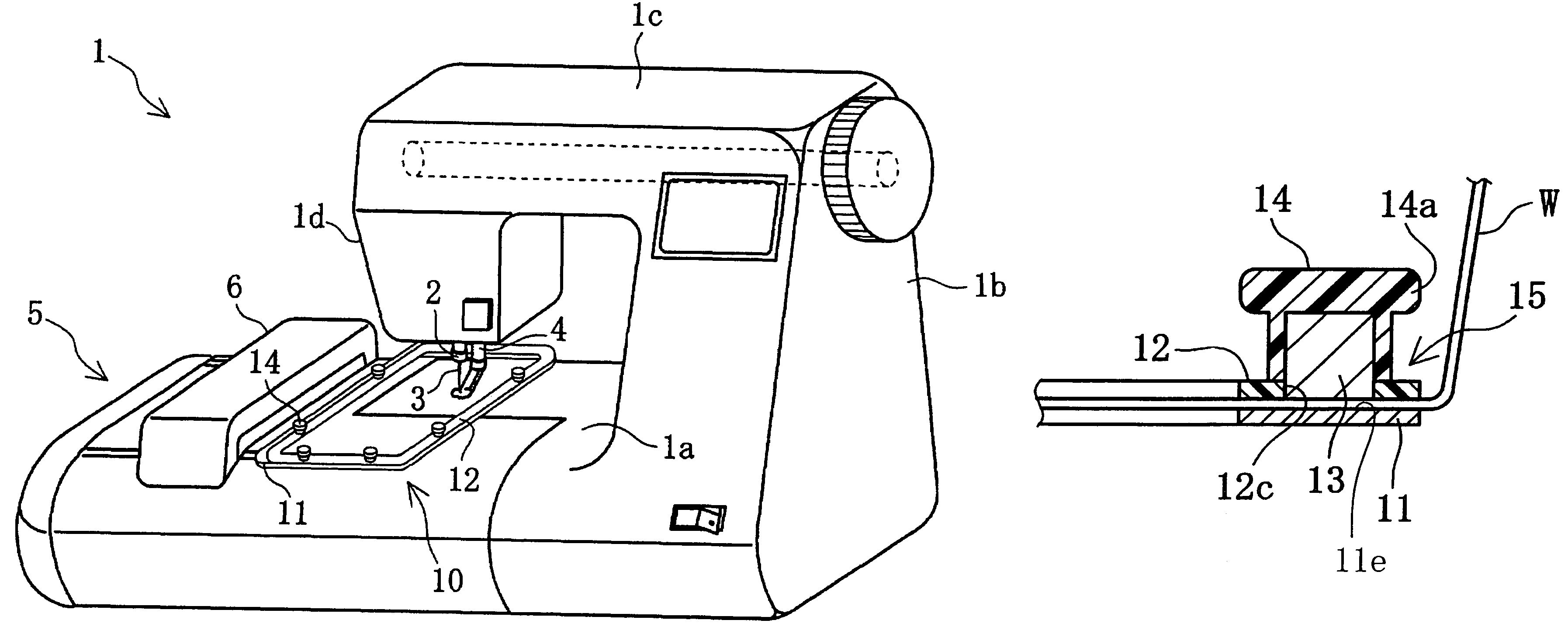
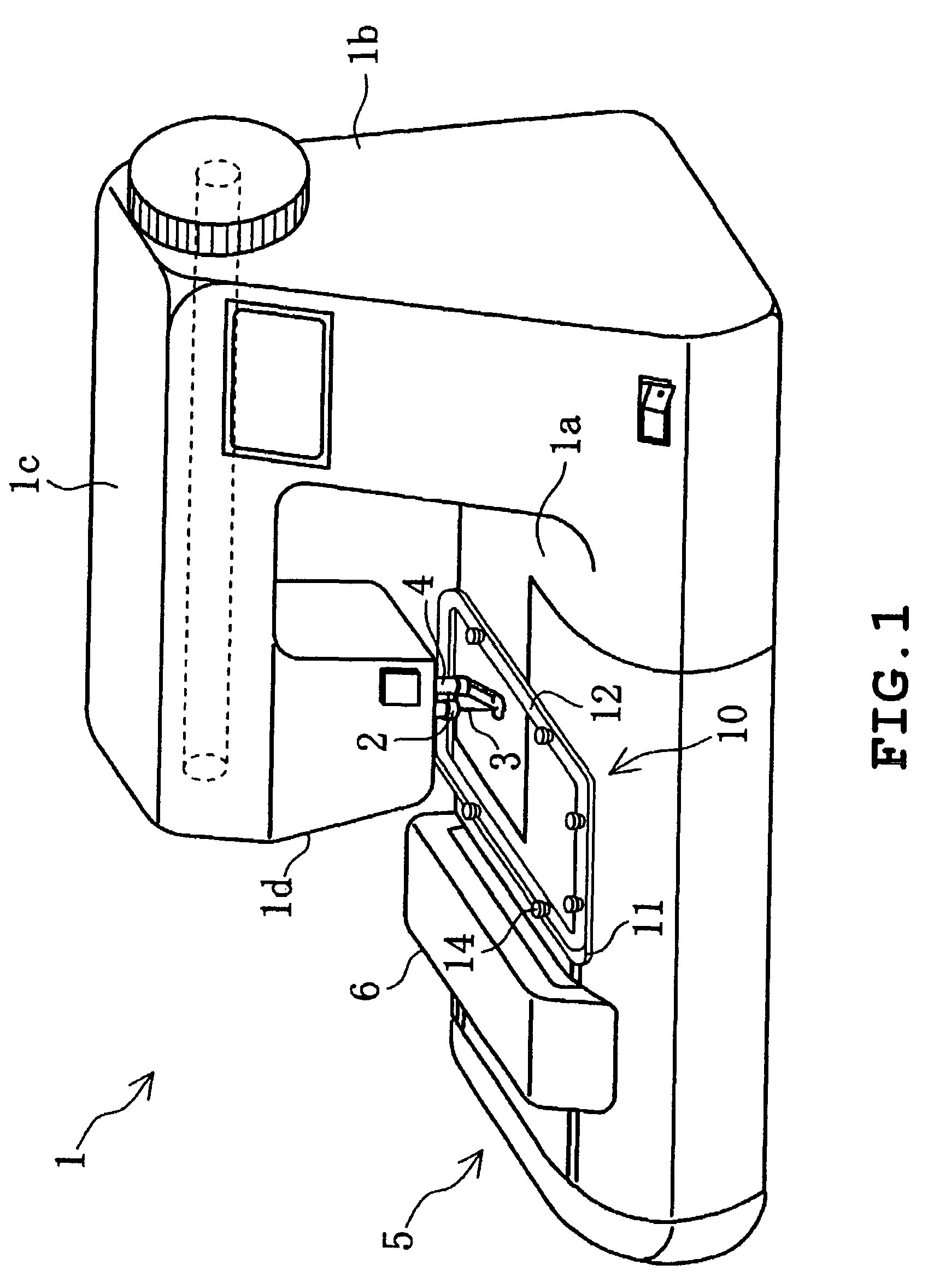
[0050]A cloth holding device 10 of the present embodiment is used in an embroidery sewing machine 1 of a type as shown in FIG. 1 for stretching and holding a workpiece cloth W to be sewn.

[0051]As shown in FIG. 1, the embroidery sewing machine 1 includes a bed 1a, a foot 1b, an arm 1c, and a head 1d. Also, a needle bar 2 with a sewing needle 3 attached to the lower end thereof is supported vertically movably to the head 1d. Also, a cloth presser 4 is supported by the head 1d. An embroidery machine 5 is provided in the bed 1a.

[0052]The embroidery machine 5 includes a movable body 6 disposed on the upper surface side of the bed 1a and supported laterally movably; a mechanism that laterally drives the movable body 6; a carriage 7 (refer to FIG. 6) supported longitudinally movably by the movable body 6; a mechanism that drives the carriage 7 in the longitudinal direction; and a connection mechanism 8 (refer to FIG...

second embodiment

[0061]FIGS. 8 to 12 indicate the second embodiment of the present invention.

[0062]The cloth holding device 20 of the present embodiment is attached to an ink-jet printer that prints the workpiece cloth. The printer is used for printing a workpiece cloth W and a part of or the entire embroidery pattern sewn by the embroidery sewing machine 1.

[0063]The cloth holding device 20 includes a support member 21 in a flat plate-form made of synthetic resin having a thickness of approximately 1 mm and a presser frame 22 made of magnetic material having a thickness of approximately 1 mm. The workpiece cloth W is clamped between the support member 21 and the presser frame 22. The support member 21 has center line indicators 21a and 21b, indicating the two intersecting center lines, formed thereto and the presser frame 22 also has center line indicators 21a and 21b, indicating the two intersecting center lines, formed thereto. When the presser frame 22 is centered and placed on the support member...

third embodiment

[0068]FIGS. 13 to 18 indicate the third embodiment.

[0069]A cloth holding device 30 of the third embodiment is employed in the embroidery sewing machine 1 of a type as shown in FIG. 1 for stretching and holding the workpiece cloth W to be sewn.

[0070]The cloth holding device 30 includes a support frame 31 made of a magnetic material having a thickness of approximately 1 mm and a presser frame 32 made of synthetic resin also having a thickness of approximately 1 mm. The workpiece cloth W is clamped between the support frame 31 and the presser frame 32. The support frame 31 assumes the same construction as the support frame 11 in the first embodiment, including a connection piece 31a having formed thereto a pair of connection hole 31b. The presser frame 32 has a vertical cross-section exhibiting a reversed U-shape, and the workpiece cloth W is pressed against the support frame 31 at the distal end portions of the opened side (underside). The support frame 31 has center line indicators 3...


PUM


Abstract

A cloth holding device including a support frame (11) made of magnetic material and a presser frame (12), clamping a workpiece cloth therebetween, including an attachment unit (13, 14) that attaches the presser frame (12) to the support frame (11) by magnetic attraction; and a positioning unit (12c) that positions the attachment unit (13, 14) to the presser frame (12).

Description

TECHNICAL FIELD[0001]The present invention relates to a cloth holding device that holds a workpiece cloth.BACKGROUND ART[0002]A conventional embroidery sewing machine generally employs an embroidery frame, having an outer frame and an inner frame fitted into the outer frame, as a cloth holding device that holds a sewing workpiece cloth in a stretched manner. The workpiece cloth is clamped between the outer frame and the inner frame fitted into the outer frame. The embroidery frame is attached to a carriage of a frame drive mechanism of the embroidery sewing machine and the frame drive mechanism feeds the cloth by driving the embroidery frame in the horizontal direction.[0003]In sewing the workpiece cloth held by the cloth holding device, a sewing pattern cannot be sewn properly when the workpiece cloth is displaced from the original positioning rendered by the workpiece cloth holding device. Thus there is a need to reinforce the capacity of the cloth holding device to hold the workp...

Claims


Application Information

Patent Timeline
Patent Type & Authority Patents(United States)
IPC IPC(8): D05C9/04D05C1/02D05B39/00
CPCD05B39/00D05C9/04D05D2207/06
Inventor KUKI, MASAKAZUKITAZAWA, HIROSHI
Owner BROTHER KOGYO KK
Why Eureka
Try Eureka