Tire with tread having continuous rib

a technology of ribs and tires, which is applied in the direction of vehicle components, transportation and packaging, non-skid devices, etc., can solve the problems of adversely affecting the rolling noise of tyres, and achieve the effects of low noise level values, high comfort, and high grip

Inactive Publication Date: 2009-02-03
PIRELLI TYRE SPA
View PDF22 Cites 16 Cited by
  • Summary
  • Abstract
  • Description
  • Claims
  • Application Information

AI Technical Summary

Benefits of technology

[0045]The tyre according to the invention ensures a high grip on wet road surfaces, very low noise level values both inside and outside the car, a high level of comfort and good handling on dry road surfaces.
[0046]In particular, in wet road conditions, where the grip is low, the tread according to the invention ensures proper drainage of the water without affecting the road holding performance, even at high speeds, both in the longitudinal direction and in the transverse (lateral) direction. This behaviour is demonstrated by the aquaplaning test around bends, during which the lateral acceleration and the maximum speed which the tyre is able to reach before loss of grip occurs, is measured. When travelling along a road curvilinear section in very wet conditions, the tyre according to the invention maintains for a longer period of time the ideal grip conditions with an increase in speed, compared to a comparative tyre.
[0047]Moreover, during lateral acceleration, there is a marked improvement in the maximum acceleration value and the maximum speed value on a wet road surface.
[0048]Therefore, the tyre according to the invention and the motorcar to which it is fitted have an optimum behaviour in wet road conditions, ensuring greater driving safety.
[0049]The high adherence between tyre and wet road surface also ensures shorter braking distances, thus improving the performance of the motor car to which the tyre is fitted.

Problems solved by technology

However, the inventors of the present invention have perceived that the presence of a considerable number of inclined grooves leading into a longitudinal groove, and their arrangement close to each other, adversely affects the rolling noise of the tyre.

Method used


Image

  • Tire with tread having continuous rib
  • Tire with tread having continuous rib
  • Tire with tread having continuous rib

Examples


Embodiment Construction

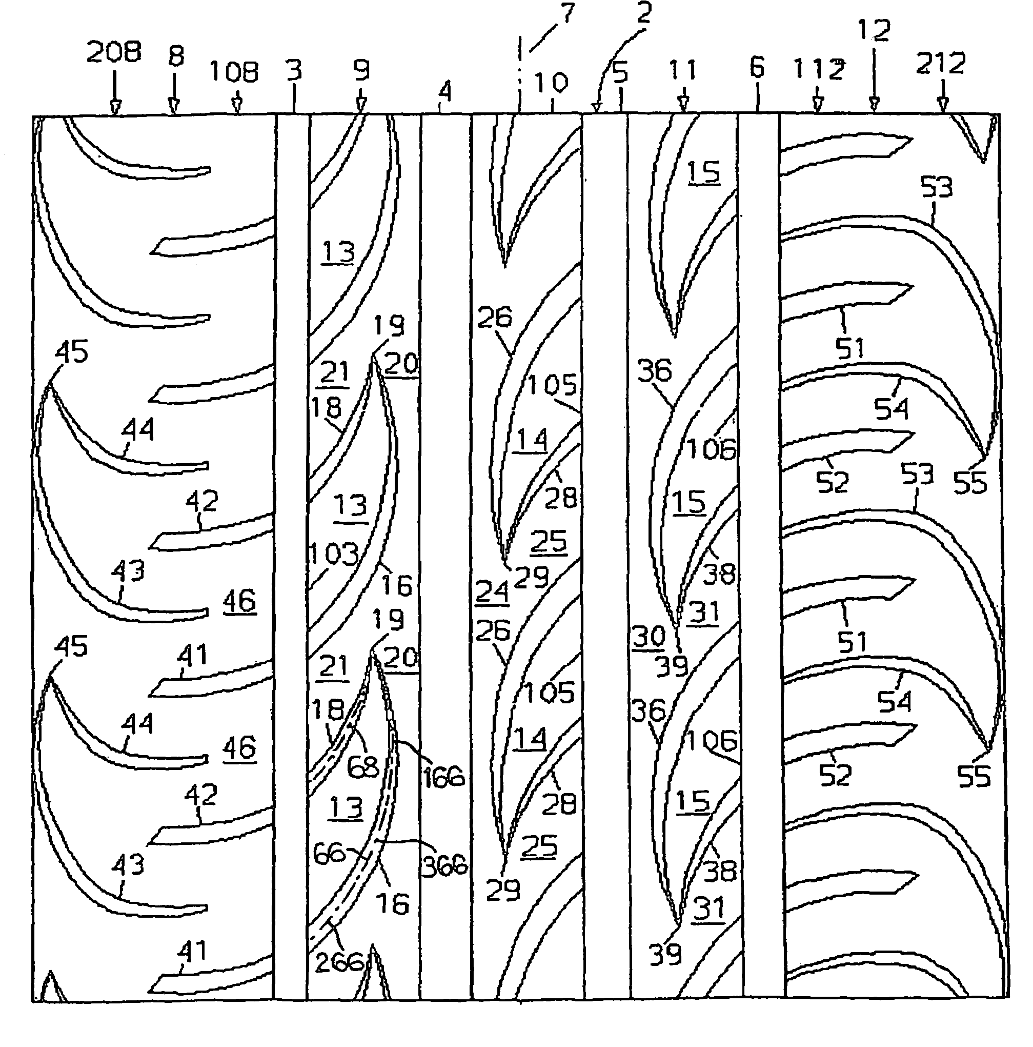
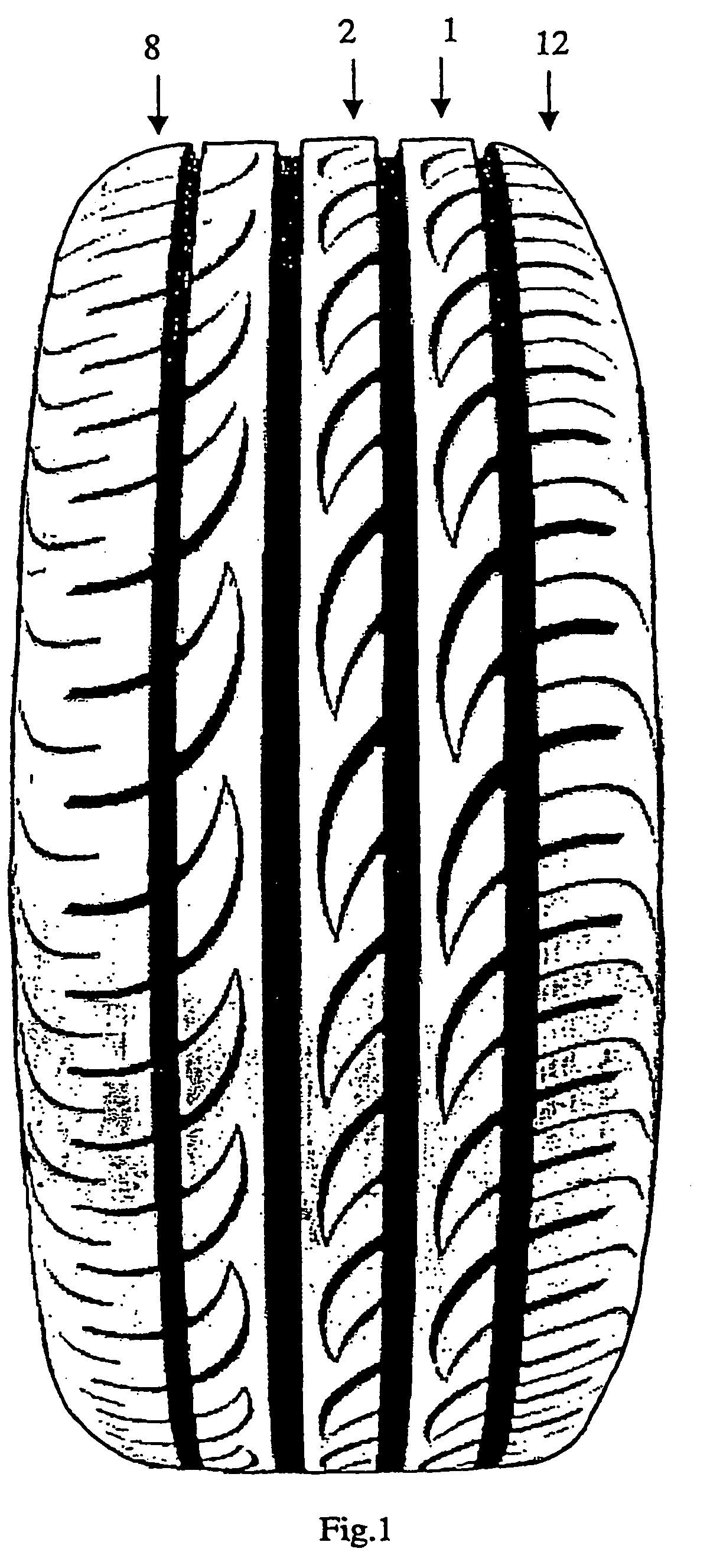
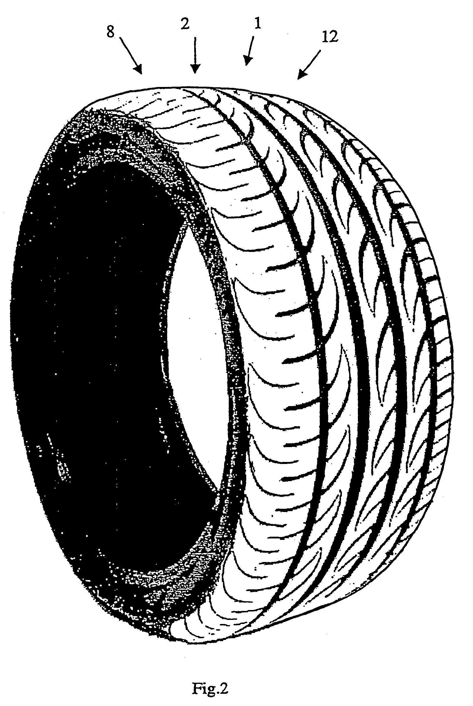
[0060]FIGS. 1 and 2 show a tyre 1 with a tread 2 axially delimited by two shoulders 8 and 12. The tread 2 is provided with circumferential grooves 3, 4, 5 and 6 (FIG. 3) which extend in longitudinal direction and are parallel to an equatorial plane 7 of the tyre. The tread 2 includes three circumferential rows of blocks 9, 10 and 11, a central row 10 and two lateral rows 9 and 11. The shoulder 8 is separated from the row of blocks 9 by means of the circumferential groove 3. The row of blocks 9 is located between the circumferential grooves 3 and 4. The row of blocks 10 is located between the circumferential grooves 4 and 5. The row of blocks 11 is located between the circumferential grooves 5 and 6. The shoulder 12 is separated from the row of blocks 11 by means of the groove 6.

[0061]The shoulders 8 and 12 comprise an axially internal region 108 and 112, respectively, said axially internal region being closer to the equatorial plane and influencing the performance of the tyre, and a...


PUM


Abstract

A tyre for a motor car includes a tread and two shoulders. The tread includes at least one circumferential row of blocks disposed between first and second circumferential grooves. Each of the blocks is delimited by a section of the first circumferential groove and by first and second transverse grooves that extend from the first circumferential groove and converge at a common vertex spaced from the second circumferential groove. The common vertex is separated from the second circumferential groove by a continuous circumferential tread rib. A second transverse groove that delimits a first block is separated from a first transverse groove that delimits a circumferentially adjacent block by a solid tread portion. The solid tread portion extends from the first circumferential groove to the circumferential tread rib and forms a single body with the circumferential tread rib, spacing the first block and the circumferentially adjacent block from each other.

Description

CROSS-REFERENCE TO RELATED APPLICATIONS[0001]This application is a national-phase entry under 35 U.S.C. § 371 from International Application No. PCT / EP02 / 02552, filed Mar. 8, 2002, in the European Patent Office, the contents of which are relied upon and incorporated herein by reference; additionally, Applicants claim the right of priority under 35 U.S.C. § 119(a)-(d) based on patent application No. 01201232.4, flied Mar. 30, 2001, in the European Patent Office; further, Applicants claim the benefit under 35 U.S.C. § 119(e) based on provisional application No. 60 / 280,762, filed Apr. 3, 2001, in the U.S. Patent and Trademark Office.BACKGROUND OF THE INVENTION[0002]1. Field of the Invention[0003]The present invention relates to a tyre for a motor car. In particular, a high-performance motor car.[0004]2. Description of the Related Art[0005]Motor vehicle tyres having a tread provided with blocks delimited by circumferential grooves extending in a substantially longitudinal direction and ...

Claims


Application Information

Patent Timeline
Patent Type & Authority Patents(United States)
IPC IPC(8): B60C11/03B60C11/04B60C11/11B60C11/13
CPCB60C11/0302B60C11/0306B60C11/0309B60C11/042B60C11/11B60C11/13B60C11/03B60C2011/0383Y10S152/901B60C2011/0374B60C2011/0388B60C11/04B60C2011/0381B60C11/0304B60C11/033
Inventor COLOMBO, GIANFRANCOCUCCO, GIANCARLOBELLO, VITO
Owner PIRELLI TYRE SPA
Why Eureka
Try Eureka