Overrunning radial coupling assembly and method for controlling the engagement of inner and outer members of the assembly

a technology of radial coupling and assembly, which is applied in the direction of friction clutches, clutches, freewheel clutches, etc., can solve the problems of adding cost and complexity to the selectable clutch, and the difficulty of external control of the clutch plate, etc., to achieve the effect of reducing the above-mentioned cost, complexity and control concerns

Active Publication Date: 2009-02-03
MEANS IND INC
View PDF39 Cites 177 Cited by
  • Summary
  • Abstract
  • Description
  • Claims
  • Application Information

AI Technical Summary

Benefits of technology

[0018]An object of the present invention is to provide an overrunning radial coupling assembly and method for controlling the engagement of inner and outer members of the assembly wherein plates or members of the assembly are designed to minimize the above-noted cost, complexity and control concerns.
[0019]In carrying out the above object and other objects of the present invention, an overrunning radial coupling assembly is provided. The assembly includes an inner member having an outer peripheral surface and an outer member having an inner peripheral surface adjacent the outer peripheral surface in radially inner and radially outer relationship. At least one of the members is mounted for rotation about a first axis. The assembly also includes pawl-receiving portions and pawl-holding portions formed on the members. The assembly further includes at least one free-floating, forward pawl and at least one free-floating, reverse pawl adjacent to the at least one forward pawl. The pawls are received and retained in the pawl-holding portions but not physically secured to the pawl-holding portions. The forward and reverse pawls are movable between an engaged position between the pawl-receiving and pawl-holding portions and a disengaged position in which one of the members is permitted to free-wheel relative to the other of the members. The assembly includes a set of biasing members carried by the pawl-holding portions and urging the forward and reverse pawls outwardly from their respective pawl-holding portions. The assembly also includes a single control element mounted for controlled, shifting movement between the surfaces relative to the pawl-holding portions and operable to control position of at least one of the pawls. The control element has at least one opening which extends completely therethrough to allow the forward and reverse pawls to extend therethrough to the engaged position in a first position of the control element to fully lock the inner and outer members together to prevent relative rotation between the inner and outer members in either direction about the first axis. The control element maintains at least one of the pawls in its disengaged position in a second position of the control element.
[0039]Still further in carrying out the above object and other objects of the present invention, a method of controlling the engagement of inner and outer members is provided. The inner member has an outer peripheral surface. The outer member has an inner peripheral surface adjacent the outer peripheral surface in radially inner and radially outer relationship. At least one of the members is mounted for rotation about a first axis. Pawl-receiving portions and pawl-holding portions are formed on the members. The method includes providing at least one free-floating, forward pawl and at least one free-floating, reverse pawl adjacent to the at least one forward pawl. The pawls are received and retained in the pawl-holding portions but not physically secured to the pawl-holding portions. The method further includes urging the forward and reverse pawls outwardly from their respective pawl-holding portions. The method includes providing a single control member between the inner and outer surfaces which is rotatable about the first axis relative to the pawl-holding portions. The control member has at least one opening which extends completely therethrough. The method further includes rotating the control element relative to the pawl-holding portions about the first axis. The at least one opening allows the pawls to extend therethrough and be received within the pawl-receiving portions in a first angular position of the control element to fully lock the inner and outer members together to prevent relative rotation between the inner and outer members in either direction about the first axis. The control element maintains at least one of the pawls in a disengaged position in a second angular position of the control element in which one of the members is allowed to free-wheel relative to the other member during the rotation of the one of the members in a first direction about the first axis. The members are locked to each other in a second direction opposite the first direction about the first axis in the second angular position.

Problems solved by technology

One way to control such sets of opposed struts or keys is to provide two slide or control plates which add cost and complexity to the selectable clutch.
Such plates may be difficult to control external to the clutch.

Method used


Image

  • Overrunning radial coupling assembly and method for controlling the engagement of inner and outer members of the assembly
  • Overrunning radial coupling assembly and method for controlling the engagement of inner and outer members of the assembly
  • Overrunning radial coupling assembly and method for controlling the engagement of inner and outer members of the assembly

Examples


second embodiment

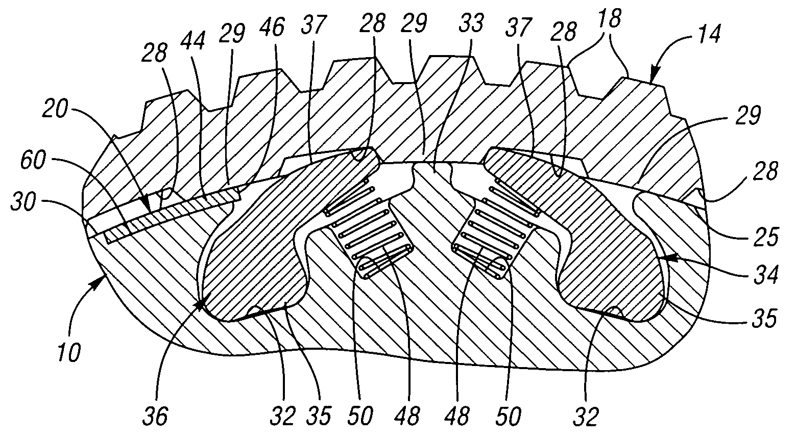
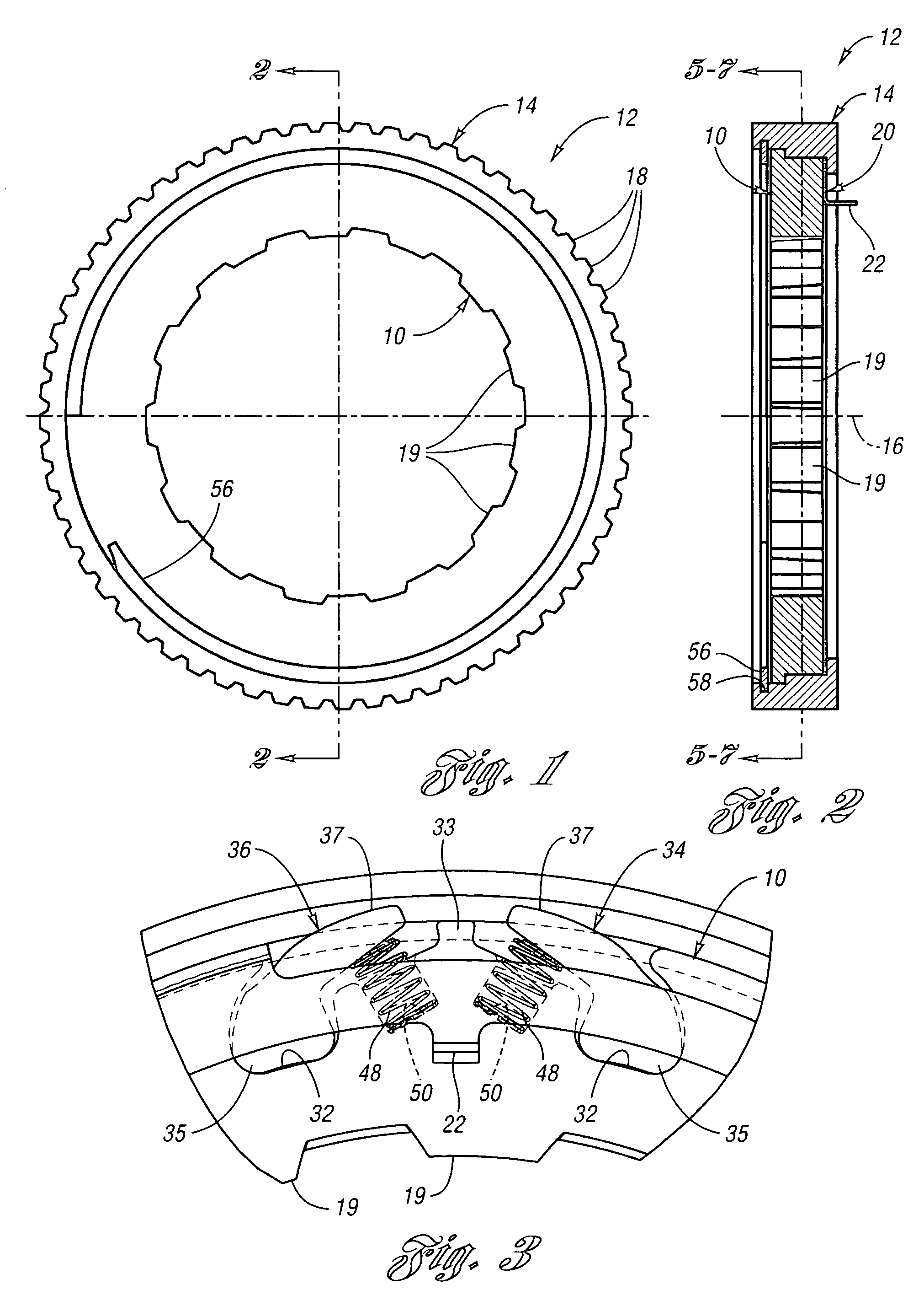
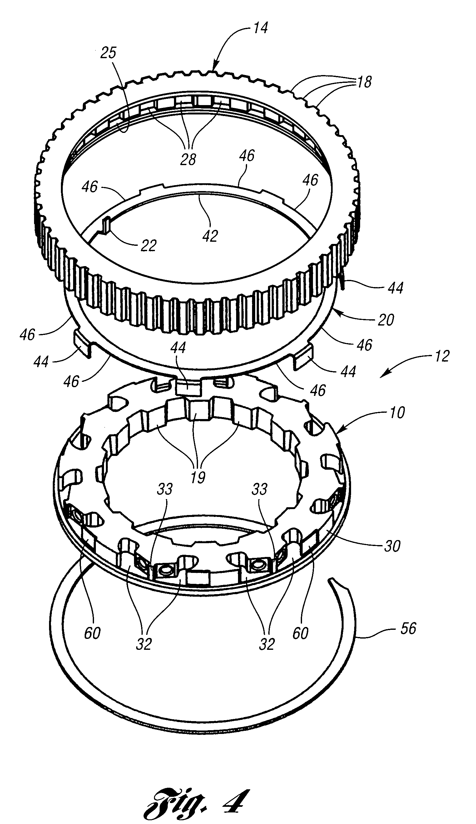
[0087]FIGS. 8 and 9 show a notch plate or inner member, generally indicated at 10′, of a overrunning radial coupling or clutch assembly, generally indicated at 12′, constructed in accordance with the present invention. An outer member or pocket plate, generally indicated at 14′, is mounted for rotation about a first axis 16′ and is located adjacent the notch plate 10′ in radially inner and radially outer relationship. The pocket plate 14′ may be drivably connected to a source of torque (not shown). This driving connection is established by external splines 18′ formed on the pocket plate 14′, which drivably engage splines on the source torque. The notch plate 10′ may be stationary or rotatable about the first axis 16′ and is provided with internal splines 19′.

[0088]Referring now to FIG. 9, an actuator (not shown) may be drivably connected to a slide or control element or plate, generally indicated at 20′, via a slide plate lever 22′, which is connected to the control member or plate ...

third embodiment

[0102]FIGS. 14 and 15 show an external plate or inner member, generally indicated at 10″, of a overrunning radial coupling or clutch assembly, generally indicated at 12″, constructed in accordance with the present invention. An outer member or plate, generally indicated at 14″, is mounted for rotation about a first axis 16″ and is located adjacent the inner plate 10″ in radially inner and radially outer relationship. The outer plate 14″ may be drivably connected to a source of torque (not shown). This driving connection is established by external splines 18″ formed on the outer plate 14″, which drivably engage splines on the source torque. The inner plate 10″ may be stationary or rotatable about the first axis 16″ and is provided with internal splines 19″.

[0103]Referring now to FIGS. 15 and 16, an actuator (not shown) may be drivably connected to a slide or control element or plate, generally indicated at 20″, via a slide plate lever 22″, which is connected to the control member or ...


PUM


Abstract

The overrunning radial coupling assembly or clutch and a method of controlling the engagement of inner and outer plates or members of the assembly are provided wherein adjacent engaging radial locking pawls are selectively controlled by a single, rotatable control plate or element to obtain full lock, one-way lock and one-way overrun conditions. The assembly includes free-floating, forward pawls and free-floating, reverse pawls adjacent to their respective forward pawls. The forward and reverse pawls are movable between a notch-engaging, engaged position (i.e., full lock condition) and a disengaged position in which the outer member is permitted to free-wheel relative to the inner member in the one-way overrun condition in one direction about a first axis and the outer member is locked to the inner member in the one-way lock condition in the opposite direction. A number of different embodiments of the assembly and method are provided.

Description

CROSS-REFERENCE TO RELATED APPLICATIONS[0001]This application is a continuation-in-part of U.S. application Ser. No. 11 / 148,910 filed Jun. 9, 2005, now U.S. Pat. No. 7,258,214 and entitled “Overrunning Coupling Assembly And Method For Controlling The Engagement of Planar Members.”BACKGROUND OF THE INVENTION[0002]1. Field of the Invention[0003]This invention relates to overrunning radial coupling assemblies such as clutches and methods for controlling the engagement of inner and outer members of the assemblies.[0004]2. Background Art[0005]Overrunning coupling assemblies may be used for transferring torque from a driving member to a driven member in a variety of structural environments. This permits the transfer of torque from a driving member to a driven member while permitting freewheeling motion of the driving member relative to the driven member when torque is interrupted. Such couplings often comprise an outer race concentrically disposed with respect to an inner race, the outer ...

Claims


Application Information

Patent Timeline
Patent Type & Authority Patents(United States)
IPC IPC(8): F16D41/16
CPCF16D41/12F16D41/125F16D41/16F16D41/14
Inventor PAWLEY, BRICE A.SMITHWICK, BRIAN W.
Owner MEANS IND INC
Why Eureka
Try Eureka