
Axle journal mounted to axle tube and method of assembly

Inactive Publication Date: 2009-02-03
SAF HOLLAND GMBH
View PDF21 Cites 6 Cited by
  • Summary
  • Abstract
  • Description
  • Claims
  • Application Information

AI Technical Summary

Benefits of technology

[0004]This invention therefore proposes a wheel bearing of the type described which is simple both from a manufacturing and assembly aspect and at the same time functionally durable.
[0006]In this manner, the clamping forces are transferred from the connecting section of the axle journal to the end section of the axle tube over a large surface so that even in the case of low clamping forces there is a very secure connection between the axle journal and axle tube. Moreover, the assembly and disassembly of such a wheel bearing can be carried out easily and quickly.
[0011]The bracing of the clamping body on the connecting section can easily be achieved by threading a section of the axially threaded bolt to an internally threaded section of the clamping piece. The threaded bolt rotates on the axle journal to prevent co-rotation of the clamping piece.
[0013]It is advantageous to reinforce the axle tube area away from the brake bracket against the rest of the axle tube to ensure secure absorption of the radial expansion forces.

Problems solved by technology

However, such flange connections are not suitable for the absorption of the considerable forces encountered in commercial vehicles.
However, this wheel bearing requires considerable manufacturing and assembly effort and can, moreover, lead to an undesired expansion of the end section of the axle tube.

Method used


Image

  • Axle journal mounted to axle tube and method of assembly
  • Axle journal mounted to axle tube and method of assembly
  • Axle journal mounted to axle tube and method of assembly

Examples


Embodiment Construction

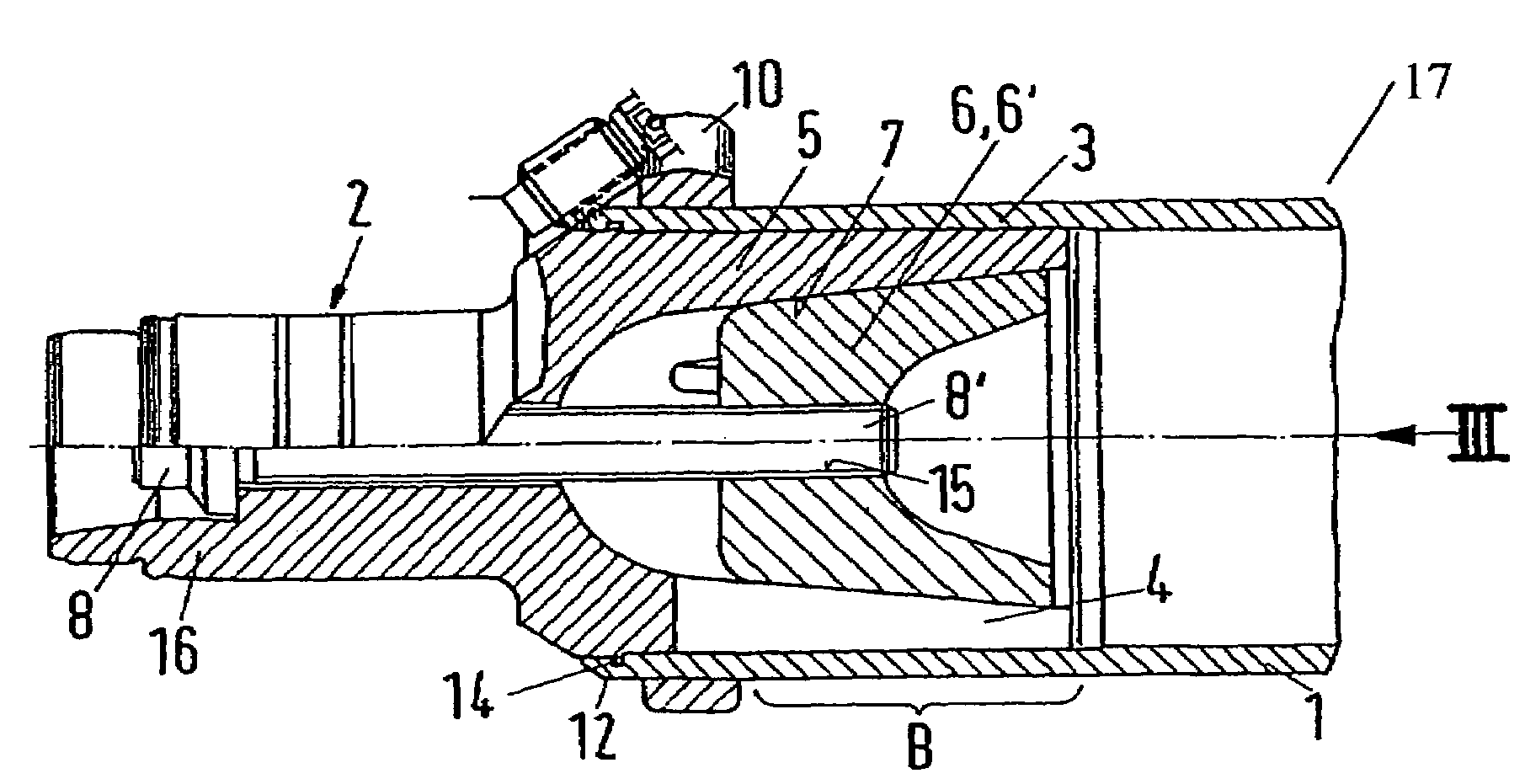
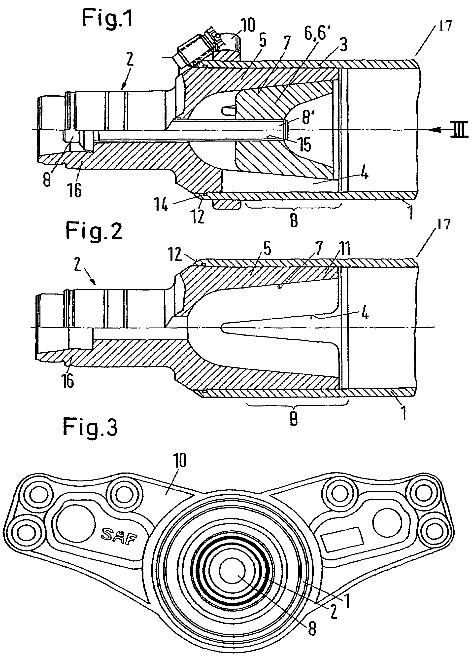
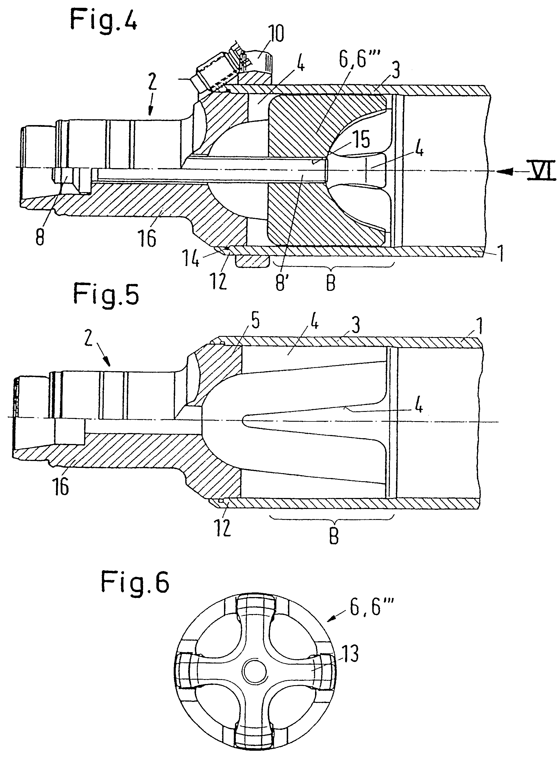
[0023]As shown in FIGS. 1-3, a wheel bearing according to the present invention is provided on an axle housing in the form of an axle tube 1 for vehicles, particularly commercial vehicles. With such a wheel bearing, the wheel (not shown) is attached, for example, by means of wheel bolts (also not shown) to a wheel hub (not shown) which is rotatably mounted on the axle journal 2 of the axle tube 1. The axle journal 2 is radially clamped on to the end section 3 of the axle tube 1 as a separate component. For this purpose, the inside of the end section 3 of the axle tube 1 is cylindrical. The axle journal 2 fits into the end section 3 of the axle tube 1 with an externally cylindrical connecting section 5. An O-ring 14 is disposed between the connecting section 5 and the axial tube 1.

[0024]The end section 3 of the axle tube 1 is radially clamped on to the connecting section 5 of the axle journal stub 2 by means of at least one clamping piece 6 that is adjustable in an axial direction re...


PUM


Abstract

The invention concerns a method for mounting a wheel on an axle housing in the form of an axle tube (1) for vehicles, in particular commercial vehicles, whereby the wheel is fixed e.g. with wheel bolts to a wheel hub, rotating on the axle journal (2) of the axle tube (1). The axle journal (2) is clamped on to an end section (3) of the axle tube (1) as a separate component. For simplicity of manufacture and assembly combined with functional durability it is proposed that the end section (3) of the axle tube (1) is cylindrical on the inside and that the axle stub (2) fits into the end section (3) of the axle tube (1) with an externally corresponding cylindrical connecting section (5). Further, the end section (3) of the axle tube (1) is radially clamped on to the connecting section (5) of the axle stub (2) by at least one clamping piece (6) that is adjustable in an axial direction to the end (12) of the axle tube (1) by a threaded bolt (8).

Description

BACKGROUND OF THE INVENTION[0001]The invention relates to a wheel bearing on an axle housing in the form of an axle tube for vehicles, in particular commercial vehicles, in which the wheel is fixed, for example, with wheel bolts, to a wheel hub, which is rotatable on the axle journal of the axle tube. The axle journal is clamped, as a separate component, on to an end section of the axle tube.[0002]For passenger vehicles, a method is known whereby the axle journal is connected to the axle housing by means of flange connections. The purpose thereof is to shift the interface between the wheel, wheel hub and axle housing, i.e. at the wheel bearing, to a location between the axle journal and the axle housing so that if the brake disc needs replacement, the mounting of the wheel, i.e. the wheel bearing, is not affected, because it never needs to be taken out. However, such flange connections are not suitable for the absorption of the considerable forces encountered in commercial vehicles....

Claims


Application Information

Patent Timeline
IPC IPC(8): B60B35/00B60B35/08
CPCB60B35/006B60B35/02B60B35/08B60B2310/305B60B2310/306B60G2204/149B60G2206/31B60G2206/50
Inventor DANTELE, JOHANN
Owner SAF HOLLAND GMBH
Learn More