Adjustable optical pickup actuator

a technology of optical pickup and actuator, which is applied in the direction of information storage, instruments, data recording, etc., to achieve the effect of facilitating data access to optical recording media and ensuring accuracy

Inactive Publication Date: 2009-02-03
TOPRAY MEMS
View PDF3 Cites 0 Cited by
  • Summary
  • Abstract
  • Description
  • Claims
  • Application Information

AI Technical Summary

Benefits of technology

[0005]The present invention has been made to overcome the above-mentioned drawback of conventional optical pick actuator. The primary object of the present invention is to provide an electromagnetic actuator for objective lens including the functions of focusing, tracking and tilt angle adjustment so that the control to the optical pickup is more precise and data access to the optical recording media is more efficient.
[0008]The present invention further includes a cover above the yoke protrudes of the yoke base. The cover covers the magnets and the coils to improve the stability of the magnetic-flux.
[0009]Compared with the conventional electromagnetic actuator, the present invention provides the tilt function in addition to focusing and tracking functions. The present invention can therefore provide more flexibility and precision in controlling the pickup device.

Problems solved by technology

However, both patents only provided focusing and tracking deviation rectification, while the tilting angle control function is not provided.

Method used


Image

  • Adjustable optical pickup actuator
  • Adjustable optical pickup actuator
  • Adjustable optical pickup actuator

Examples


Embodiment Construction

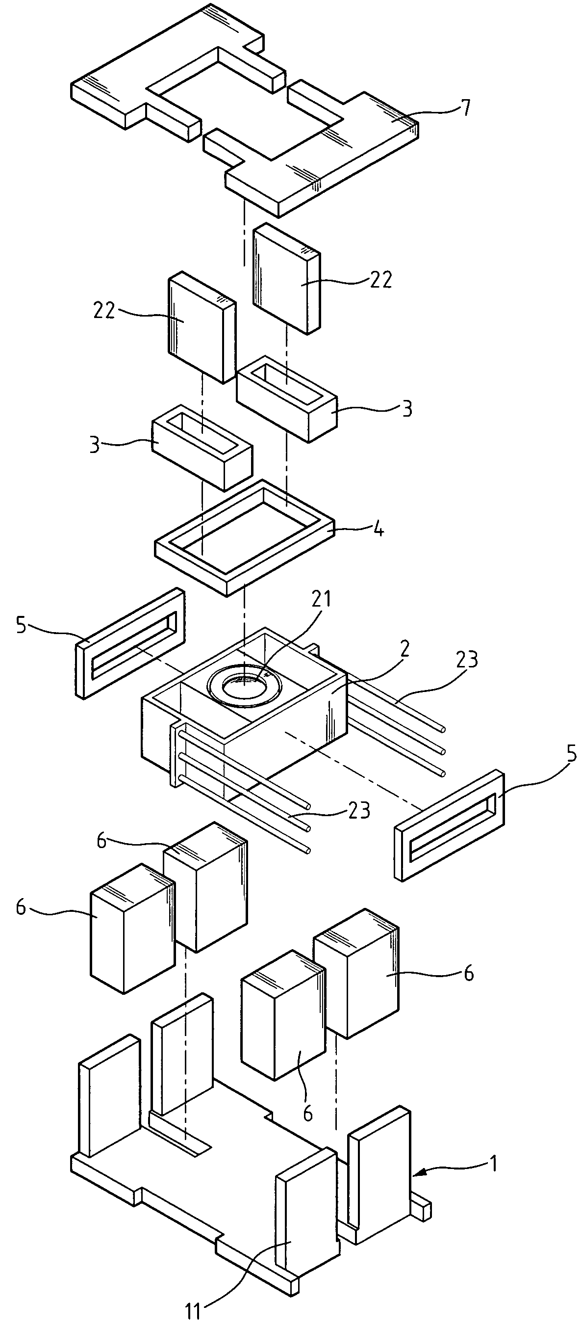
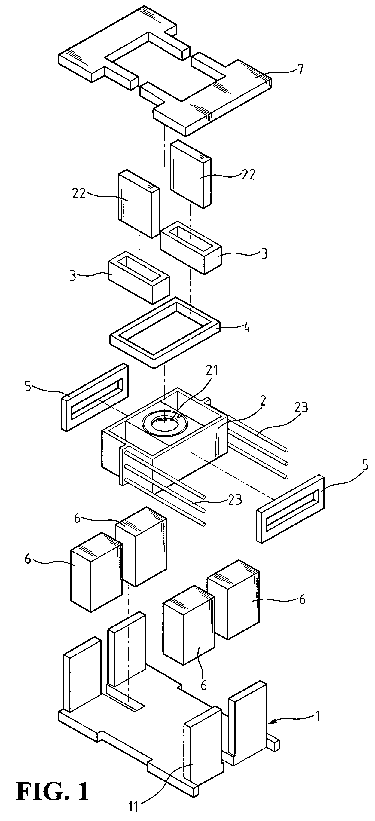
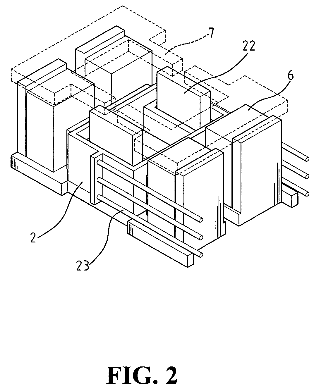
[0017]Refer to FIGS. 1-4. An actuator of the present invention includes a yoke base 1, a lens holder 2, two focusing coils 3, two tracking coils 5, a tilting coil 4, and four magnets 6. Yoke base 1 is for carrying the above elements, and the four corners of yoke base 1 include four yoke protrudes 11 extending upwards.

[0018]Lens holder 2 is a carrier with a lens 21. The two sides of lens holder 2 is attached to spring wires 23. Lens holder 2 is hanged on yoke base 1 by spring wires 23.

[0019]Two focusing coils 3 are placed on yoke protrude bumps 22 on the two opposite sides of lens holder 2. Focusing coils are perpendicular to the optical axis of lens 21 for controlling the movement of lens 21 along the focusing direction.

[0020]Tilting coil 4 is on lens holder 2 and is placed on the above yoke protrude bumps 22. The current in tilting coil 4 is perpendicular to the optical axis of lens 21 and parallel to the current in focusing coils 3. Therefore, a single coil will be sufficient to g...


PUM

PropertyMeasurementUnit
magnetic-fluxaaaaaaaaaa
currentaaaaaaaaaa
opticalaaaaaaaaaa

Abstract

An adjustable optical actuator with tilting function is provided, including two focusing coils, a tilting coil, and two tracking coils. A lens holder is hanged on a yoke base. The focusing coils are placed on the two sides of the lens holder, and the current in the focusing coils is perpendicular to the optical axis of the lens. The tilting coil is placed on the lens holder, and the current in the tilting coil is perpendicular to the optical axis of the lens. The tracking coils are placed on the lens holder, and the current in the tracking coils is parallel to the optical axis of the lens. Four magnets are placed on the yoke base so that the four magnets are placed at the four corners of the lens holder to generate a closed magnetic-flux. The lens holder, focusing coils, tilting coil, and tracking coils are within the scope of the magnetic-flux generated by the four magnets so that the actuator has the functions of focusing, tracking and tilting for adjustment.

Description

FIELD OF THE INVENTION[0001]The present invention generally relates to a CD-ROM player, and more specifically to a structure of an adjustable optical actuator of a CD-ROM player.BACKGROUND OF THE INVENTION[0002]The recording devices using optical recording media, such as CD-ROM or MO are an important part for data recording. All these optical devices have an optical pickup for sending light beams to the optical recording media and receiving reflected light beams from the optical recording media. The optical pickup includes a light source, such as semiconductor laser, for emitting light beam, and a lens for focusing light beam to the optical recording media. Furthermore, the optical pickup requires an actuator for driving the lens to rectify the deviation of the focus and the lens tracking so that the light beam can be precisely focused and the recording tracks can be correctly tracked.[0003]The majority of the actuators employ the electromagnetic method to drive the objective lens f...

Claims


Application Information

Patent Timeline
Patent Type & Authority Patents(United States)
IPC IPC(8): G11B7/00
CPCG11B7/093G11B7/0933G11B7/0935
Inventor CHANG, TSUNG-KAICHEN, CHIEN-KUOSHEN, PAO-HENG
Owner TOPRAY MEMS
Why Eureka
Try Eureka