Transfer apparatus and image forming apparatus

a technology of transfer apparatus and image forming apparatus, which is applied in the direction of electrographic process apparatus, instruments, optics, etc., can solve the problems of increasing voltage dependency of resistance, untimely transfer of toner image, and poor endurance performance of foamed cells exposed on the surface as in the conventional transfer apparatus, so as to achieve low voltage dependency of resistance of the transfer roller, good image quality, and high endurance performance

Inactive Publication Date: 2009-02-03
OKI DATA CORP
View PDF4 Cites 24 Cited by
  • Summary
  • Abstract
  • Description
  • Claims
  • Application Information

AI Technical Summary

Benefits of technology

[0008]Another object of the invention is to provide a transfer apparatus in which high endurance performance is obtained, the voltage dependency of the resistance of the transfer roller is minimized, and a good image quality being obtained.

Problems solved by technology

If the transfer roller has a hard surface, the toner image is not transferred normally, resulting in uneven transfer of the toner image.
Foamed cells exposing on the surface as in the conventional transfer apparatus exhibit poor endurance performance.
In other words, as the cumulated number of printed pages increases, the resistance of the transfer roller increases, and therefore the voltage dependency of the resistance increases.
This makes it difficult to control transfer current, and causes poor image quality.

Method used


Image

  • Transfer apparatus and image forming apparatus
  • Transfer apparatus and image forming apparatus
  • Transfer apparatus and image forming apparatus

Examples


first embodiment

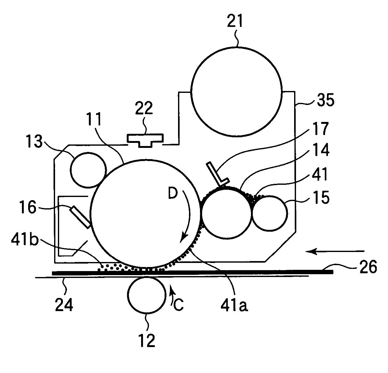
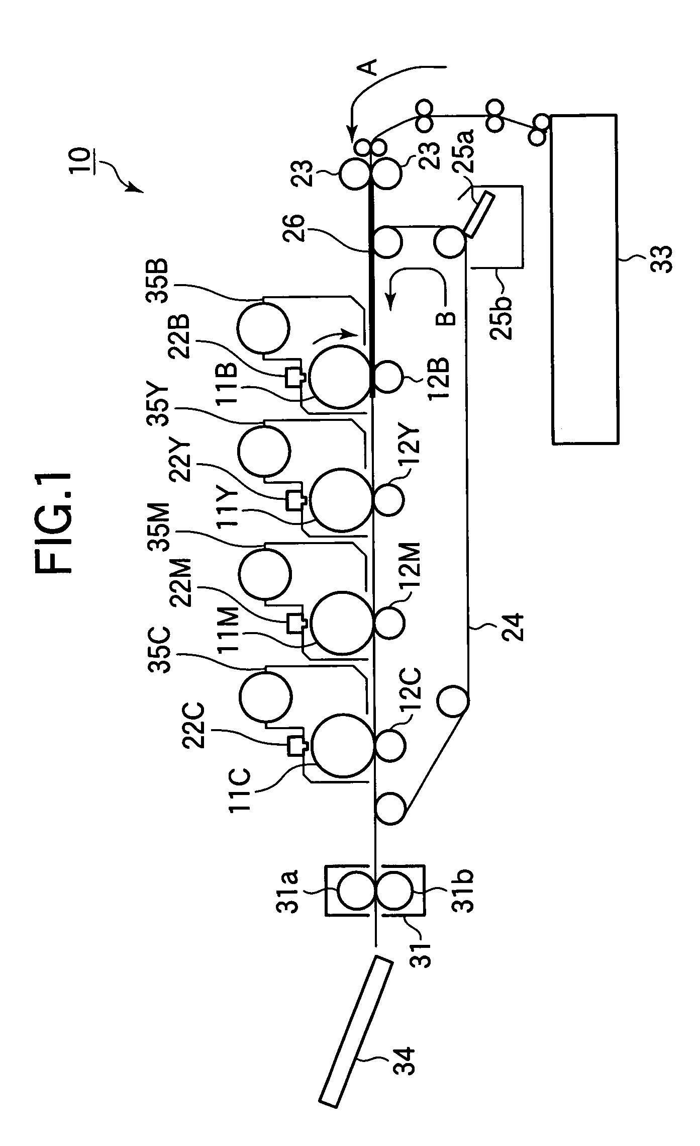
[0034]FIG. 1 illustrates a general configuration of an image forming apparatus according to a first embodiment.

[0035]Referring to FIG. 1, an image forming apparatus 10 employing electrophotography includes an electrophotographic printer, a facsimile machine, a copying machine, or a multi function peripherals (MFP) that performs as a printer, facsimile machine, and a copying machine. The image forming apparatus 10 will be described in terms of a tandem type electrophotographic color printer. An endless transfer belt 24 is entrained about a plurality of rollers. A medium is fed into a transport path and in a direction shown by arrow A and is further transported through a plurality of image forming sections as the transfer belt 24 runs.

[0036]A medium 26 is, for example, print paper or a transparency (OHP). A paper cassette 33 holds a stack of medium 26. A registration roller 23 feeds the medium 26 to the first image forming section in timed relation with image formation. Image forming ...

example 1

[0076]The endurance test was performed with the pressing force FTR set to 112 gf / cm. ΔR was 0.08 before the endurance test, and 0.29 after the endurance test. Image quality was consistently good enough.

example 2

[0077]The endurance test was performed with the pressing force FTR set to 93 gf / cm. ΔR was 0.10 before the endurance test, and 0.30 after the endurance test. Image quality was consistently good enough.


PUM


Abstract

A transfer unit transfers an image formed on an image bearing body (a photoconductive drum or an intermediate transfer belt) onto a medium by an electrostatic force. The transfer unit includes a transfer belt and a transfer roller. The transfer roller extends parallel to the image bearing body and transfers a toner image onto a medium. The transfer roller is pressed toward the image bearing body under a pressing force in a range of 28-112 gf / cm. The transfer belt is held between the transfer roller and the image bearing body in a sandwiched relation to define a transfer point between the transfer belt and the image bearing body. The transfer belt transports the medium through the transfer point.

Description

BACKGROUND OF THE INVENTION[0001]1. Field of the Invention[0002]The present invention relates to a transfer apparatus and an image forming apparatus.[0003]2. Description of the Related Art[0004]A conventional image forming apparatus incorporates a transfer roller that transfers a toner image from a photoconductive drum onto a medium such paper. If the transfer roller has a hard surface, the toner image is not transferred normally, resulting in uneven transfer of the toner image. A transfer apparatus has been proposed which uses a transfer roller having a surface formed of a foamed material. Thus, a transfer roller with less hardness can be obtained.[0005]Foamed cells exposing on the surface as in the conventional transfer apparatus exhibit poor endurance performance. In other words, as the cumulated number of printed pages increases, the resistance of the transfer roller increases, and therefore the voltage dependency of the resistance increases. This makes it difficult to control t...

Claims


Application Information

Patent Timeline
Patent Type & Authority Patents(United States)
IPC IPC(8): G03G15/16
CPCG03G15/1685G03G2215/0119
Inventor FURUYA, SATORU
Owner OKI DATA CORP
Why Eureka
Try Eureka