Automatic icemaker

a technology of automatic icemaking and ice maker, which is applied in the field of automatic icemaking machines, can solve the problems of increasing the power consumption of the freezer with a corresponding increase in the cost of ice making, the need to replace the ice trays often, and the cost of ice trays is high, so as to achieve the effect of not increasing the power consumption of the freezer, and not increasing the cost of ice trays

Inactive Publication Date: 2009-02-10
JAPAN SERVO CO LTD
View PDF14 Cites 32 Cited by
  • Summary
  • Abstract
  • Description
  • Claims
  • Application Information

AI Technical Summary

Benefits of technology

[0010]An object of the present invention, attempted to eliminate the disadvantages noted above, is to provide an automatic icemaker which allows ice pieces made in an ice-tray to be detached easily without increasing the power consumption of the freezer, having to replace the ice-tray frequently or making the ice-tray expensive.
[0012]In this automatic icemaker, residual bubbles are formed toward the bottom side of the ice partitions and, when freezing is substantially completed, the residual bubbles rupture to enable the ice pieces to freely move within the ice partitions. Therefore, power consumption by the freezer is not increased, there is no need to frequently replace the ice-tray, moreover the cost of the ice-tray is not increased, and ice pieces made in the ice partitions can be easily detached.

Problems solved by technology

However, the conventional automatic icemaker equipped with an ice detaching heater, since it applies heat to the ice-tray by using a heater within the freezer, the power consumption of the freezer increases with a corresponding rise in the ice making cost.
In the second conventional automatic icemaker which detaches ice pieces from the ice-tray by twisting the ice-tray, the repetition of the water supplying, ice making and ice discharging sequence causes frequent stresses to be applied to the ice-tray, whose durability is thereby affected, resulting in a need to replace the ice-tray frequently.
For the conventional automatic icemaker which detaches ice pieces by the deforming force of thermosensitive displacement elements which requires installation of a thermosensitive displacement element on the bottom face of each of the ice partitions, the ice-tray is made expensive.

Method used


Image

  • Automatic icemaker
  • Automatic icemaker
  • Automatic icemaker

Examples


Embodiment Construction

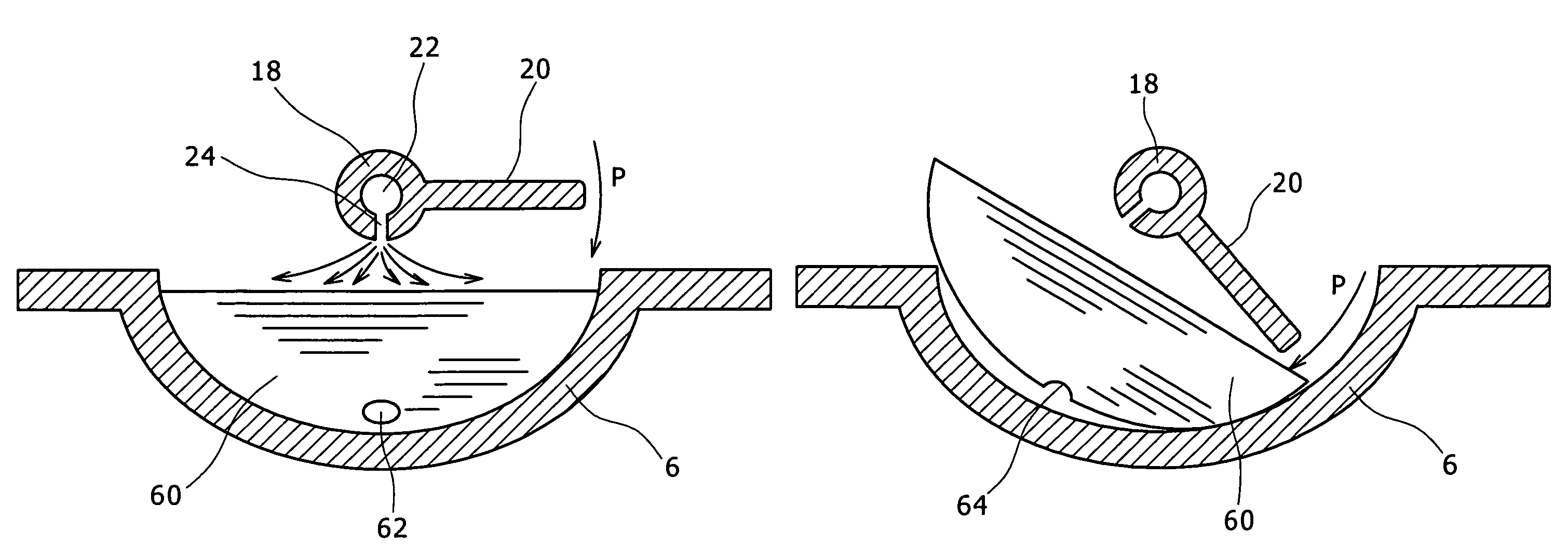
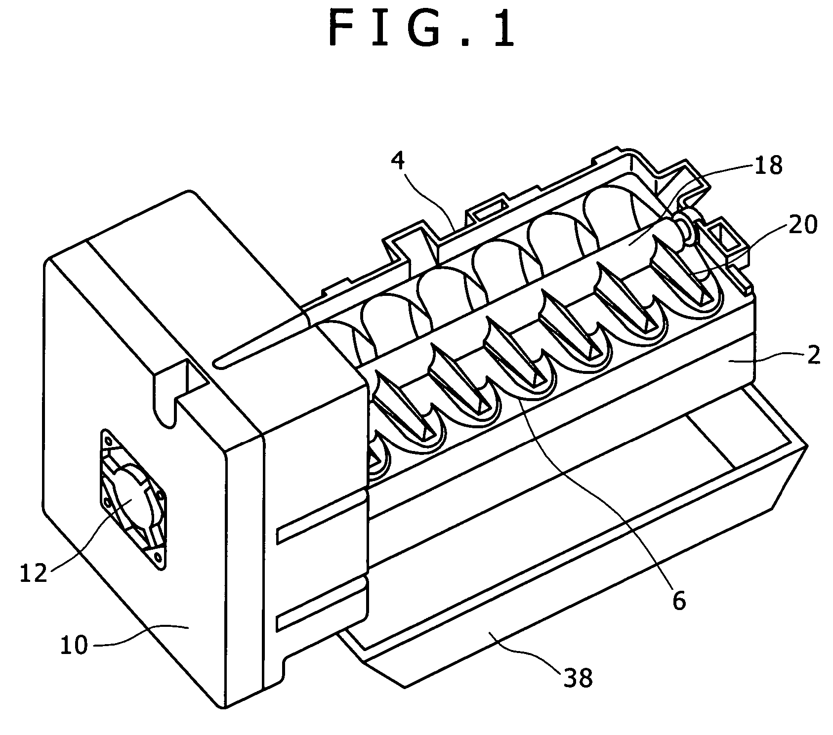
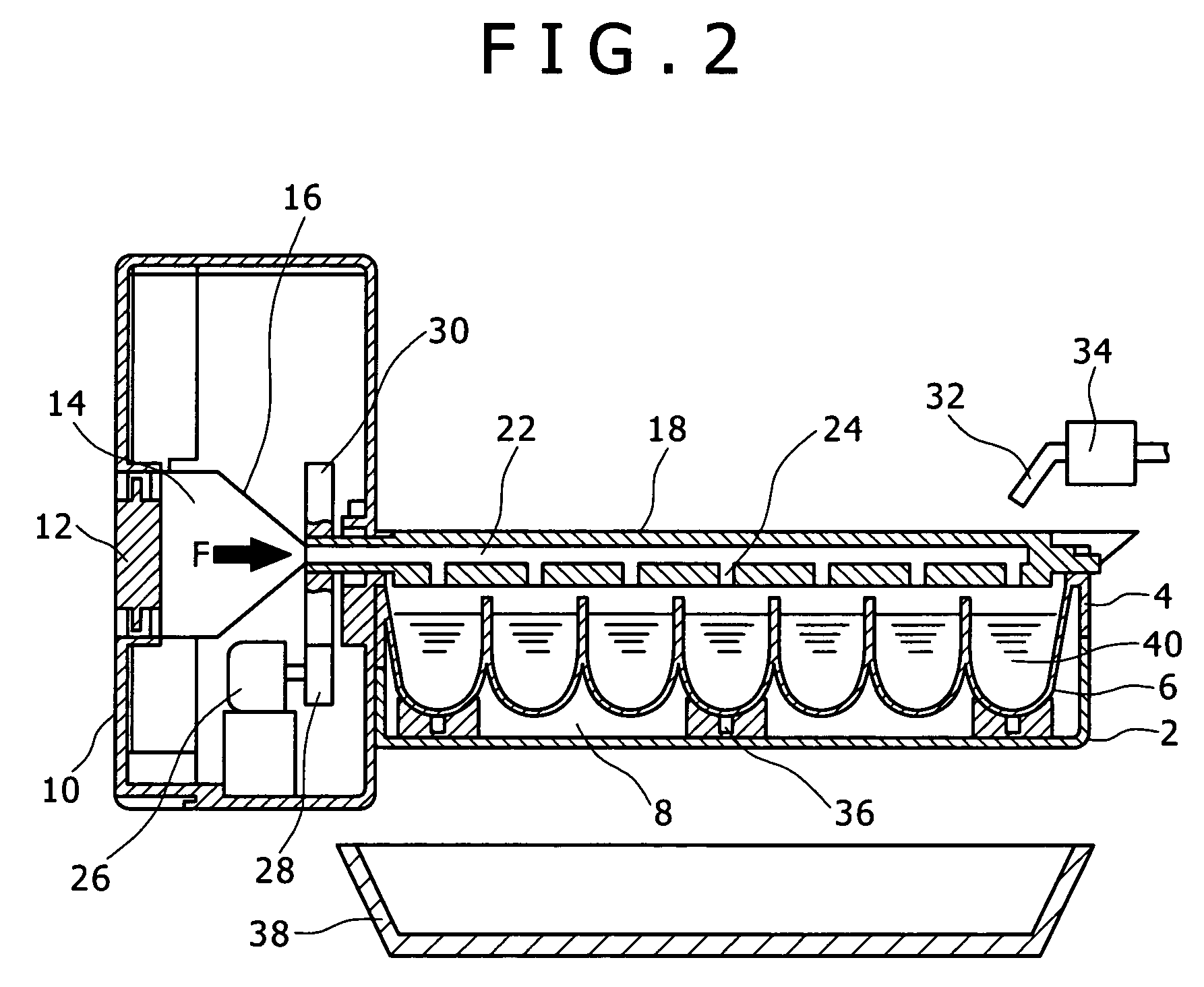
[0027]An automatic icemaker according to the invention will be described below with reference to FIG. 1 through FIG. 3. An ice-tray 4 is fitted to an outer case 2. The ice-tray 4 has a plurality of concave ice partitions 6. An air layer 8 is formed between the outer case 2 and the ice-tray 4. The air layer 8 constitutes temperature distribution forming means which forms a temperature distribution in which freezing progresses from the open side of the ice partitions 6 of the ice-tray 4 and is completed near the bottom side of the ice partitions 6. A control box 10 is fixed to the outer case 2. The control box 10 is provided with an air blower 12. A wind tunnel 14 is connected to the air blower 12. The wind tunnel 14 has a wind tunnel wall 16. A revolving body 18 is revolvably supported by the control box 10. The revolving body 18 is provided with ice discharging claws 20. The revolving body 18 further has a main air duct 22 and branch air ducts 24. The main air duct 22 communicates w...


PUM


Abstract

An automatic icemaker according to the invention can be disposed in one part of a freezer and automatically make ice pieces, and is provided with temperature distribution forming means which forms a temperature distribution in which freezing progresses from the open side of ice partitions of an ice-tray and is completed near the bottom side of the ice partitions.

Description

BACKGROUND OF THE INVENTION[0001]1. Field of the Invention[0002]The present invention relates to an automatic icemaker which carries out water supplying, ice making and ice discharging.[0003]2. Description of the Related Art[0004]A conventional automatic icemaker pours water into an ice-tray having a prescribed shape, detaches ice pieces from the ice-tray by using a heater after making the ice pieces by refrigerating the water with the cold air of the freezer, and scrapes out the ice pieces by turning an ice discharging arm with a motor.[0005]Another conventional automatic icemaker twists the ice-tray to detach the produced ice pieces more easily from the ice-tray, thereby releases the ice pieces from its adhesion to the ice-tray, and transfers the ice pieces to an ice storage box.[0006]In still another conventional automatic icemaker, a thermosensitive displacement element, typically a bimetal element or a shape memory element, whose shape varies at a temperature below 0° C., is ar...

Claims


Application Information

Patent Timeline
Patent Type & Authority Patents(United States)
IPC IPC(8): F25C1/12
CPCF25C1/04F25C5/04F25C2600/04F25D2317/061F25D2700/16F25C2305/024
Inventor SASAKI, NAOTAKASUGAYA, KENJIITO, HIDEAKI
Owner JAPAN SERVO CO LTD
Why Eureka
Try Eureka