
Sublimation containment apparatus and method for developing latent fingerprints

a technology of sublimation containment and fingerprints, applied in the direction of stamping, person identification, diagnostic recording/measuring, etc., can solve the problems of unwanted spillage, increased waste, and wrong amount of cyanoacrylate monomer applied to the pad,

Inactive Publication Date: 2009-02-10
WEAVER DAVID M +1
View PDF17 Cites 11 Cited by
  • Summary
  • Abstract
  • Description
  • Claims
  • Application Information

AI Technical Summary

Problems solved by technology

There are several disadvantages with the kits of the '579 and '515 patents.
The user must physically add the cyanoacrylate monomer to a pad or plug which may result in unwanted spillage or a wrong amount of cyanoacrylate monomer applied to the pad.
The kits also consist of multiple components which increases the complexity of using the kits as well as increases the amount of waste.
The principal disadvantages with the '645 patent is that it requires a heat resistent housing and the use of a butane torch, both requirements making the cartridge clumsy and potentially dangerous to use.
The disadvantage with these devices is that they require the use of a propane torch which increases the potential danger of using the devices.
The devices also have multiple components including the need for additional cyanoacrylate to refill the housing, which increases the maintenance of the devices.
As seen in previous devices, this apparatus is very cumbersome to carry and use in field operation, and requires the use of a separate heater and fan which increases the maintenance effort.
The disadvantage with the '946 device is that it is cumbersome to carry and use in the field.
Also, the internal size of the chamber limits the number, size, and shape of the objects that can be placed in the container for testing.

Method used


Image

  • Sublimation containment apparatus and method for developing latent fingerprints
  • Sublimation containment apparatus and method for developing latent fingerprints
  • Sublimation containment apparatus and method for developing latent fingerprints

Examples


first embodiment

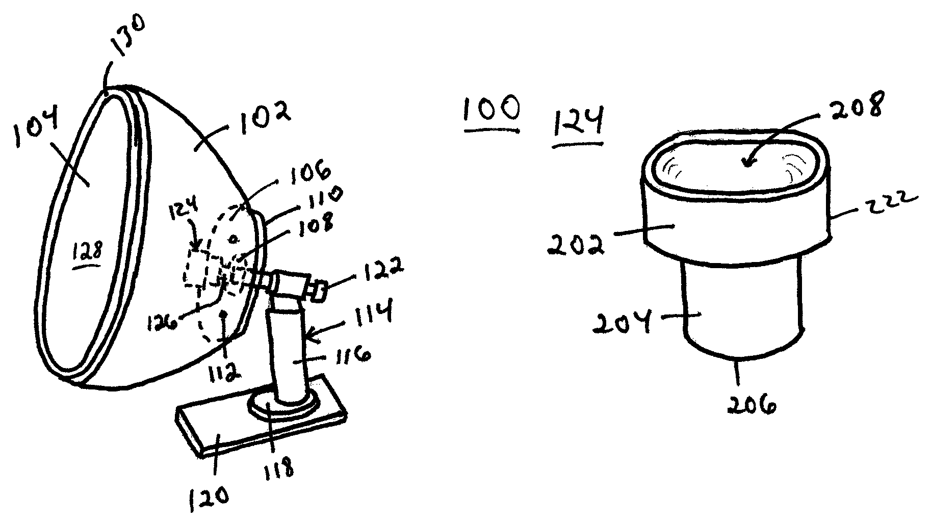
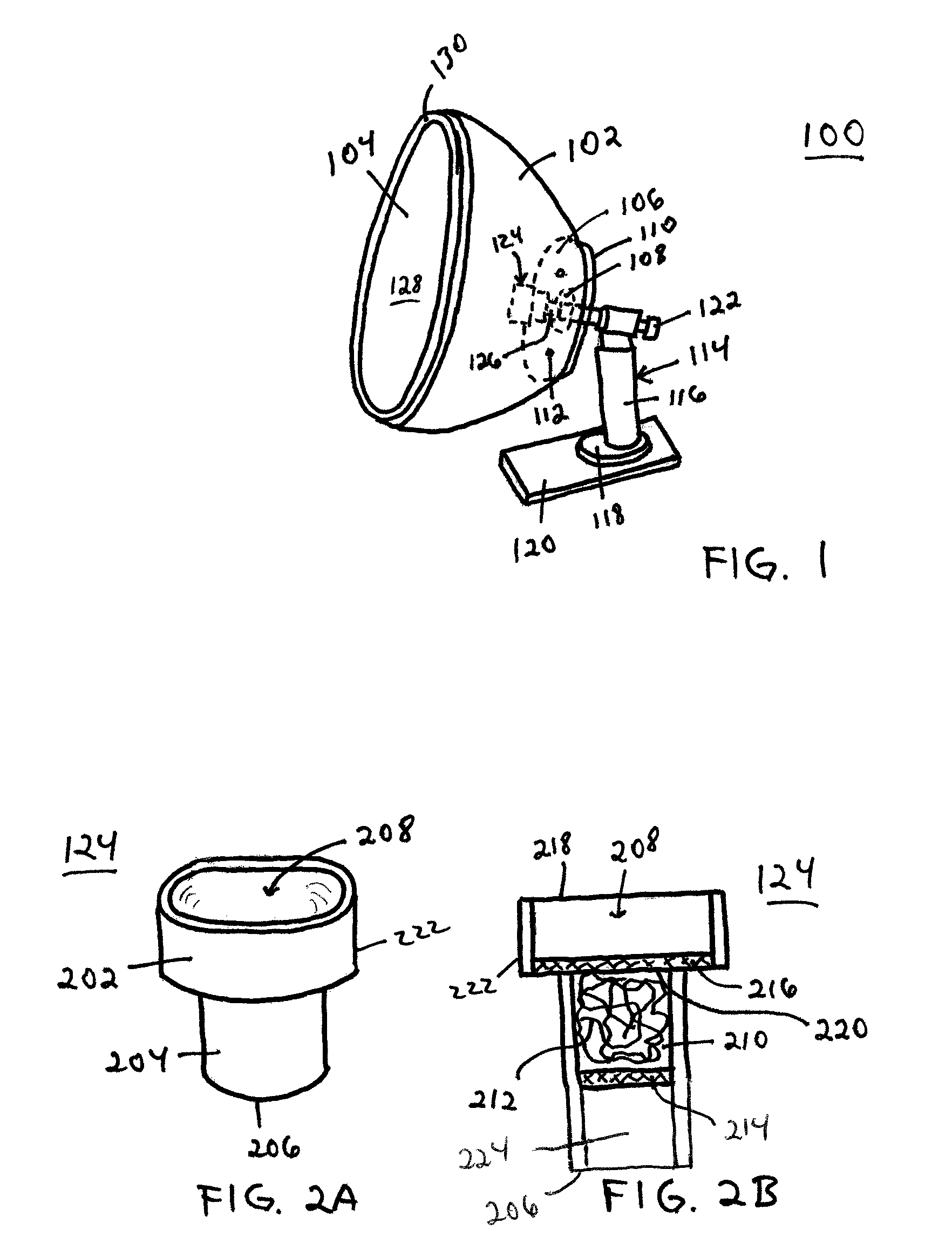
[0029]The sublimation cartridge 222 is preferably made of metal, ceramic, or glass and is about 1-2 inches in length. The sublimation cartridge 222 contains the components needed to create the cyanoacrylate vapors 306 used in developing latent fingerprints. In this first embodiment, a porous pad 212, such as a ball of steel wool, ceramic fiber, granulated loose wool, and non-granulated loose wool, is disposed within the throat cavity 210 between a first retaining screen 216 and a second retaining screen 214. The first and second retaining screens 216, 214 are preferably made of bronze metal, but this is for convenience wherein any high temperature resistance material is suitable. The first retaining screen 216 is positioned at the intersection 220 of the head 202 and throat 204, whereas the second retaining screen 214 is positioned at a point within the throat 204. The positioning of the first retaining screen 216 and the second retaining screen 214 are also for convenience.

[0030]Li...

second embodiment

[0032]In a second embodiment, the chamber 102 has a seal 130 around the perimeter edge of the open end 104. The seal 130 functions to further contain the vapors 306 within the internal space 128 by sealing the open end 104 against a surface on which the object 302 being examined is placed. The seal 130 is made of a foam or neoprene type material. Possible surfaces on which to use the apparatus 100 include the ground, a wall, furniture surface, vehicle surface, and the like.

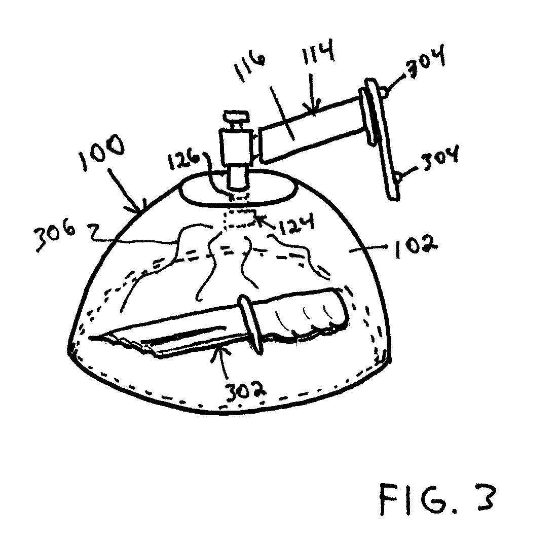
[0033]The use and operation of the apparatus 100 is shown in FIG. 3. A user turns the on / off button 122 to activate the heat source 114 which causes the generation of heat out of the heat emitting end 126 of the heat source 114. The heat activates the cyanoacrylate disposed on the porous pad 212 which in turn generates the cyanoacrylate vapors 306. The user holds the heat source 114 by the handle 116 and places the chamber 102 over the object 302, such as a weapon (knife) or other item, being examined. Latent fing...

fourth embodiment

[0041]A third and fourth embodiment of the sublimation system 124 are shown in FIGS. 6-8 which also uses the chamber 402 shown in FIG. 4. A pair of tethers 702, 704 is connected to the edge 606 of the entry aperture 602 of a chamber 600 by mechanical fasteners 706, 708. The pair of tethers 702, 704 are each preferably a metal wire. In addition, a pair of tethers 702, 704 are used for convenience. It would be readily apparent to one of ordinary skill in the art to use one or more tethers, or a comparable means for securing the chamber 600 to a heat source 114.

[0042]In FIGS. 6 and 7, the sublimation systems 700, 800 further comprise a small porous pad 710, such as steel wool, secured to the intersection of the pair of tethers 702, 704. Alternatively, in FIG. 8, the sublimation system 800 further comprises a porous platform 802, such as a metal or plastic mesh screen, secured to the pair of tethers 702, 704 overlaying the intersection of the tethers 702, 704. Then, liquid or solid cyan...


PUM

PropertyMeasurementUnit
lengthaaaaaaaaaa
diameteraaaaaaaaaa
transparentaaaaaaaaaa

Abstract

An apparatus and method for developing latent fingerprints having a heat source with a removably mounted chamber and sublimation system wherein the sublimation system is in communication with a heat emitting end of the heat source and an internal space of the chamber. Upon activating the heat source, heat transforms a cyanoacrylate of the sublimation system into vapor within the internal space of the chamber. The vapor contacts an object contained within the chamber to reveal any latent fingerprints on the object.

Description

CROSS-REFERENCE TO RELATED APPLICATION[0001]This application claims the benefit of U.S. Application No. 60 / 740,953 filed on Nov. 29, 2005, and U.S. Application No. 60 / 817,167 filed on Jun. 27, 2006.BACKGROUND[0002]1. Technical Field[0003]The present invention relates to apparatuses for developing latent fingerprints and the method of use thereof, and in particular, to the use of a chamber in combination with a heat source and a sublimation system containing a cyanoacrylate wherein the application of heat transforms the cyanoacrylate to vapor which is used in the quick and efficient development of latent fingerprints on objects contained in the chamber.[0004]2. Related Art[0005]The use of cyanoacrylate in the development of latent fingerprints on objects is well known and has been used as such for many years. Specifically, it is the reaction of the cyanoacrylate monomer and a catalyst that creates a microcrystalline vapor which adheres to fingerprints. Once the vapor cures, the cyano...

Claims


Application Information

Patent Timeline
Patent Type & Authority Patents(United States)
IPC IPC(8): A61B5/117C23C16/00C23C16/448C23C16/455
CPCA61B5/117A61B5/1172
Inventor WEAVER, DAVID M.WEAVER, ORDIS G.
Owner WEAVER DAVID M
Learn More