Shingle processing tool and method

a technology of asphalt shingles and tools, applied in the direction of manufacturing tools, band saws, saw chains, etc., can solve the problems of excessive heat generation, significant damage to the apparatus, and affecting the cutting speed of asphalt shingles, so as to achieve the desired product efficiently and efficiently cut asphalt shingles

Inactive Publication Date: 2009-02-10
SANDVIK INTELLECTUAL PROPERTY AB
View PDF11 Cites 13 Cited by
  • Summary
  • Abstract
  • Description
  • Claims
  • Application Information

AI Technical Summary

Benefits of technology

[0010]The present invention fills the aforementioned needs by providing a method and apparatus for efficiently cutting asphalt shingles, thereby efficiently producing the desired product without melting the asphalt shingles.

Problems solved by technology

These wood-grinding apparatus work well grinding wood, but when grinding asphalt shingles they create excessive frictional heat that melts the shingles, thereby hindering the grinding and causing significant damage to the apparatus, as explained below.
The excessive heat is produced because the grinding apparatus inefficiently processes the extremely abrasive asphalt shingles.
Also, as the shingles must reach approximately one inch in diameter, they cycle around the inside of the screened container, thereby creating more friction.
The shingles are cut and raked repeatedly until they are small enough to exit through the screen, thereby creating the excessive frictional heat that melts the shingles.
When the shingles melt inside the processing apparatus, the apparatus becomes bound and damages the drum-driving motor and the cutting heads.
Also, the apparatus will not function again until the melted asphalt is removed, which is costly and time consuming.
The available wood-grinders are too inefficient and create too much friction, thereby creating high temperatures that melt the asphalt shingles before the desired byproduct is produced.
The above noted problems are clearly evidenced by the fact that it was only commercially viable to use that apparatus to grind asphalt shingles in an extremely cold environment, such as the far northern hemisphere during winter, where extremely low temperatures prevented the shingles from melting during grinding.

Method used


Image

  • Shingle processing tool and method
  • Shingle processing tool and method
  • Shingle processing tool and method

Examples


Embodiment Construction

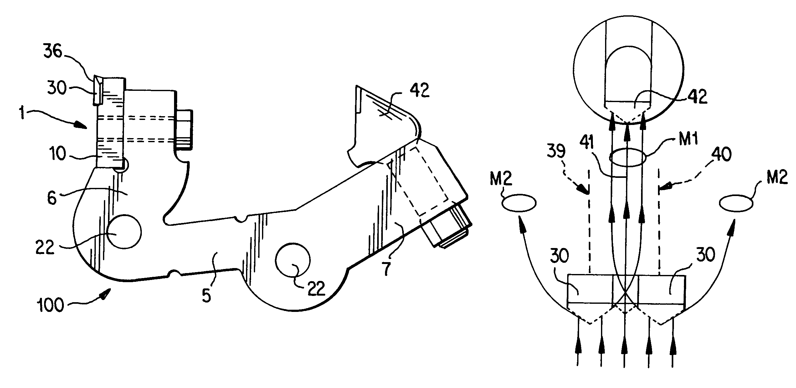
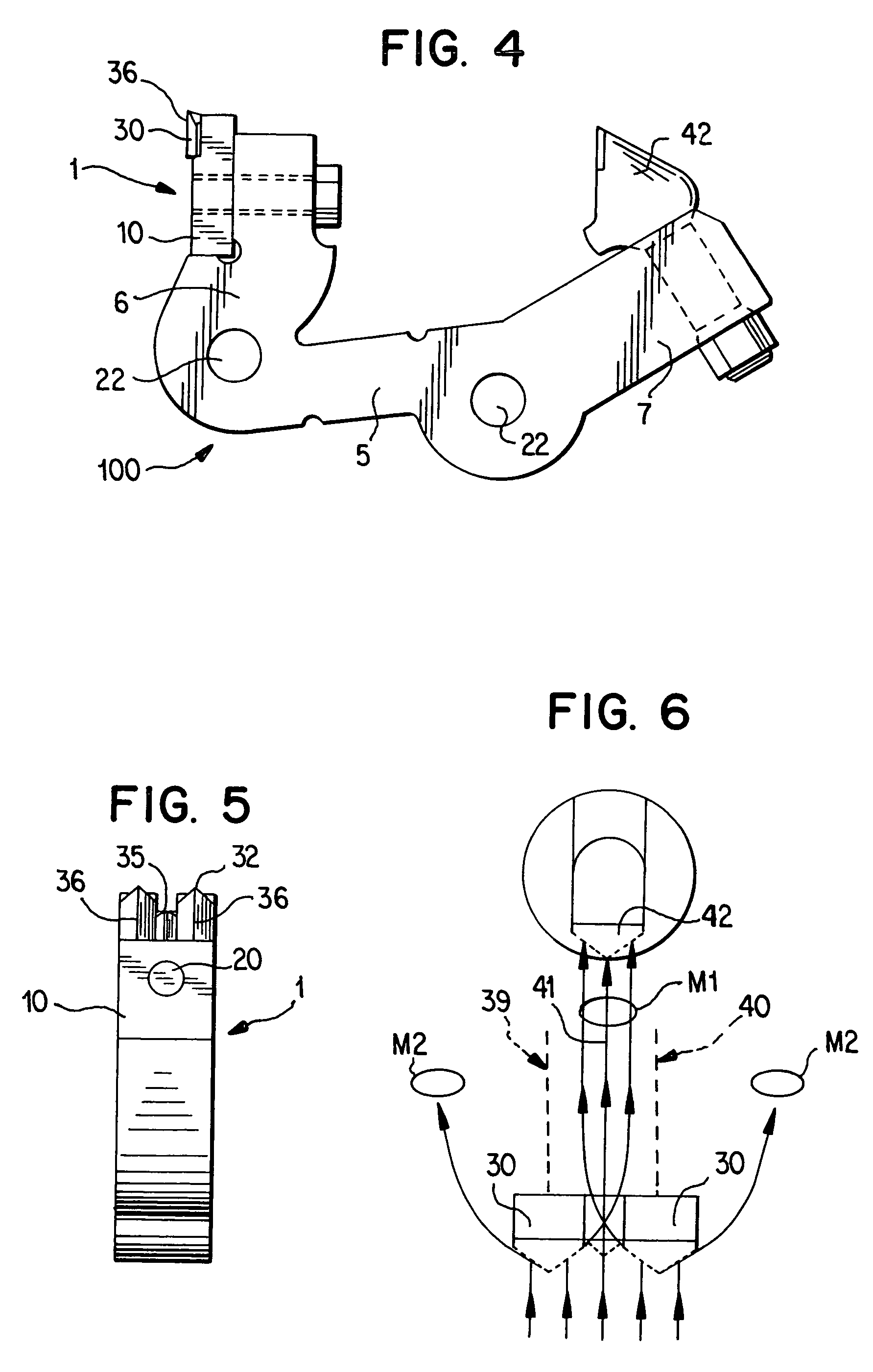
[0019]In the present invention, the prior art's raker has been replaced by a tool configured to cut the material being processed, and to funnel the cuttings into the path of a rear cutting tool trailing between and behind the teeth. Materials, such as asphalt shingles, can now be cut with less friction, thus minimizing any melting of the shingles.

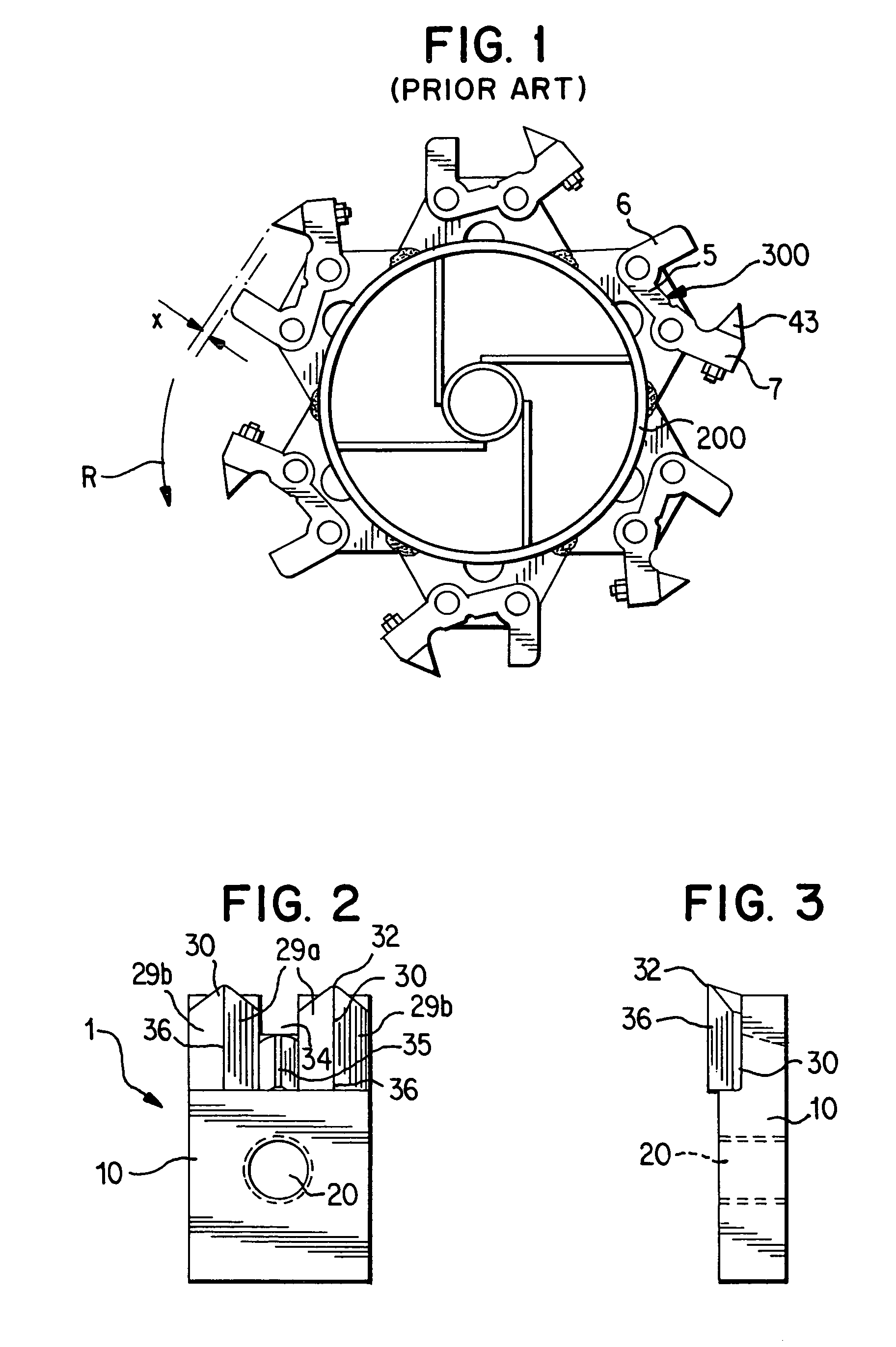
[0020]FIG. 2 illustrates a front view of one preferred embodiment of the cutting tool 1, as the tool 1 would be “seen” by an asphalt shingle being processed. The tool 1 would be attached to the base 5 of a cutting head 100 as shown in FIG. 4. A plurality of such cutting heads would be mounted on a drum, as shown in FIG. 1, e.g., in circumferentially and axially spaced relationships as is conventional. This embodiment of the cutting tool 1 includes a holder body 10 and two cutting teeth 30 extending from the body 10 substantially parallel to one another. The teeth 30 are preferably brazed in a notch formed in an edge of the body. Each tooth ...


PUM

PropertyMeasurementUnit
diameteraaaaaaaaaa
leading areaaaaaaaaaaa
stabilityaaaaaaaaaa

Abstract

A cutting tool for attachment to the leading area of a base is provided. The cutting tool includes a holder base having two substantially parallel cutting teeth extending from the holder base, the cutting teeth each having a cutting edge and an opening between the teeth. The cutting teeth define first and second cutting paths. The cutting teeth impact and cut asphalt shingles, and funneling surfaces of the teeth funnel the cut shingle material toward and through the opening, and into the path of the rear cutting member which cuts the material a second time. Thus, asphalt shingles are processed more efficiently, thereby creating less frictional heat and avoiding melting of the asphalt shingles.

Description

FIELD OF THE INVENTION[0001]The present invention relates generally to material processors and to methods of processing material, such as asphalt shingles.BACKGROUND OF THE INVENTION[0002]It is well known in the art that adding a mixture of 4-10% recycled asphalt shingle by-product to road pavement enhances the pavement's stability, reduces cracking of the pavement, and increases the pavement's durability. Therefore, a demand exists for such by-products of recycled asphalt shingles and it is desirable to efficiently and economically grind asphalt shingles into byproduct for use in road pavement.[0003]It has been previously known in the art to use wood-grinding apparatus to grind asphalt shingles. A wood grinding apparatus generally employs a large rotating drum with grinding heads attached to the outside of the drum. The drum is located inside an outer container having a screened portion. The screened portion allows wood chips to exit through the screen once they are small enough.[0...

Claims


Application Information

Patent Timeline
Patent Type & Authority Patents(United States)
IPC IPC(8): B02C13/00
CPCB02C13/2804B02C18/18B28D1/188B28D1/26Y10T83/04Y10T83/0448Y10T83/9319
Inventor MONYAK, KENNETH
Owner SANDVIK INTELLECTUAL PROPERTY AB
Why Eureka
Try Eureka