Sulky shaft connector device

a technology of shaft connector and sulky, which is applied in the field of racing sulky harnesses, can solve the problems of sulky wheels oscillating, sulky to lift upwardly, and hinder the horse's natural running gait, so as to achieve significant more natural gait, maintain maximum speed, and quick fit

Inactive Publication Date: 2009-02-10
GODDARD RON +3
View PDF14 Cites 10 Cited by
  • Summary
  • Abstract
  • Description
  • Claims
  • Application Information

AI Technical Summary

Benefits of technology

[0012]The present invention reduces the difficulties and disadvantages of the prior art by providing a sulky shaft connector device for use with a racing sulky harness that allows a racehorse harnessed thereto to reach and maintain maximum speed with a significantly more natural gait. To achieve this, a novel ball and socket connection allows a frame, to which the harness is connected, to damply slide along a vertical path of travel relative to a sulky shaft end and to also rotate laterally relative thereto. Moreover, the device is quick fit to allow easy assembly and disassembly from the sulky shaft via a male-female type sulky shaft connector member that is also removably connected to the sulky shaft. The rounded profile of the male end ensures a self-alignment of the two mating connector member parts. Advantageously, this arrangement significantly reduces the workload placed on the horse during a race and increases the horse's athletic performance, while significantly reducing injuries to the horse's upper body and lower legs.

Problems solved by technology

The rider's center of mass is typically located behind the wheel axles, which causes the sulky to lift upwardly at the sulky shafts and hinder the horse's natural running gait.
Moreover, the horse's natural running gait causes the horse's sides lateral torso to move up and down during full forward and rearward limb extensions, with the force of this action being transferred to the sulky wheels via the harness connector and the sulky frame thereby causing the sulky wheels to oscillate.
The aforesaid factors combine to decrease the efficiency of the horse's running form, which in turn can significantly reduce the speed and comfort of the horse.
Moreover, current sulky designs and the track's banking combine to cause upper body and lower leg injuries to the horse.
This may significantly reduce the racing career of the horse and cause costly veterinarian bills.
The aforesaid designs suffer from a number of important drawbacks.
Disadvantageously, none of the designs appears to be of sufficient flexibility in the harness system to allow the horse's movements to be independent of the sulky shafts.
Some of the designs are of a complex construction, which may add mass to the harness.
In addition, some designs appear to be only suitable for statically connecting the sulky shafts to the harness and may be unsuitably inflexible to allow independent cushioning of the sulky shafts during normal racing conditions.
Furthermore, the designs all appear to rely on an interference fit between the sulky shaft end and the harness connector, which may not be suitable to enable independent extension and retraction of the sulky shafts during racing and banking.

Method used


Image

  • Sulky shaft connector device
  • Sulky shaft connector device
  • Sulky shaft connector device

Examples


Embodiment Construction

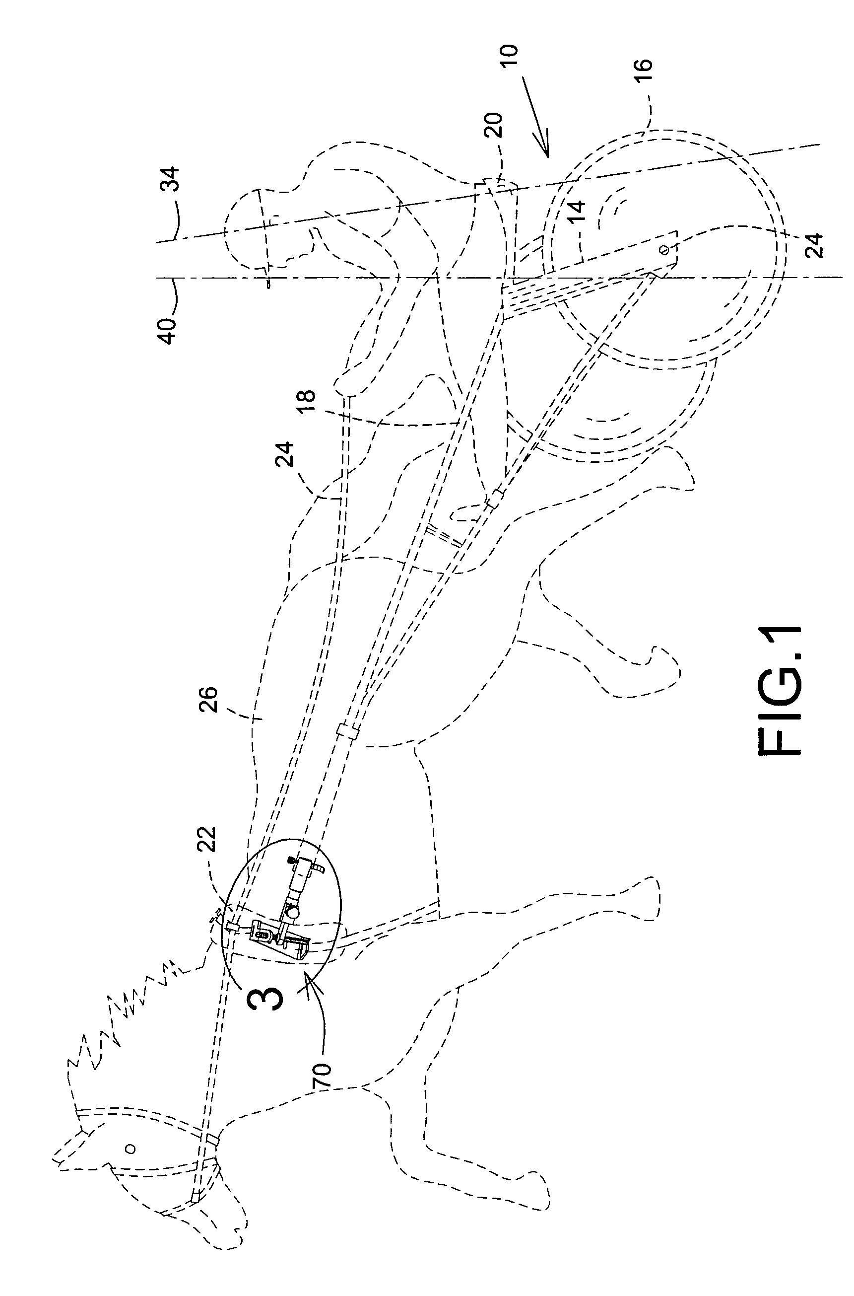
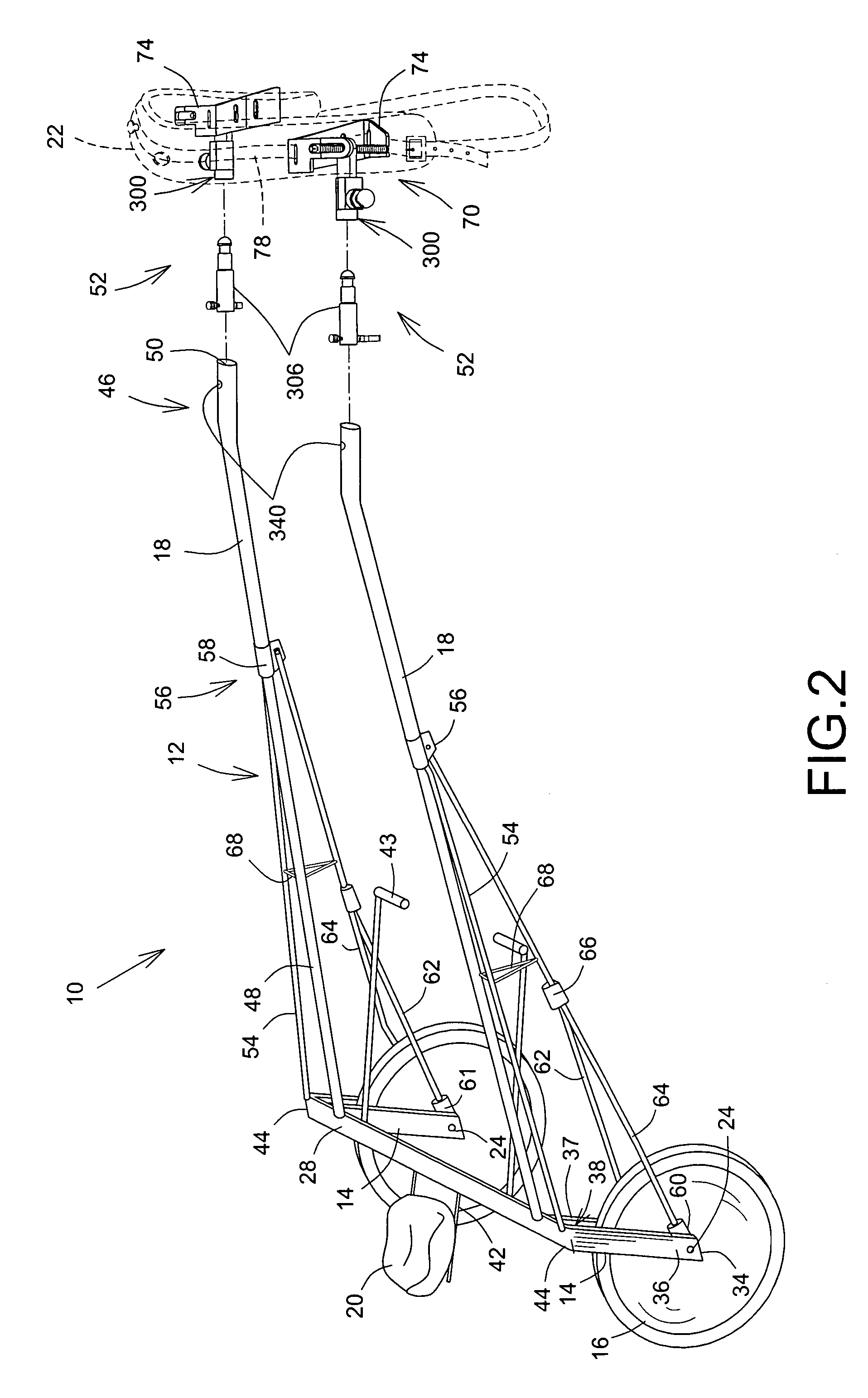
[0023]Referring now to FIGS. 1 and 2, a racing sulky is shown generally at 10. Broadly speaking, the sulky 10 includes a frame 12, a pair of forks 14, a pair of wheels 16, two elongate sulky shafts 18 and a seat 20. A harness 22 and reins 24 respectively provide a means of connecting the sulky 10 to a horse 26 and controlling the horse 26.

[0024]The frame 12 includes a rear cross connector bar 28 to which the two forks 14 are connected. Typically, the forks 14 are welded to the cross connector bar 28, but maybe part of a single piece of material which is machined and formed into the two forks 14. In accordance with the present invention, the forks 14 are angled away from the rear end 30 of the horse 26 and locate a rider's center of mass 34 behind the wheel's axles 24. Since both forks 14 are essentially identical, only one will be described in detail. The fork 14 includes two spaced apart struts 36, 37 that form a gap 38 of sufficient width to allow the wheel 16 to be mounted thereb...


PUM


Abstract

A sulky shaft connector device includes a swivel ball joint arrangement whereby the sulky shaft is allowed relative damped vertical movement with respect to the harness. A sulky shaft connector member, removably connected to the sulky shaft, forming part of the device also provides for quick and releasable engagement between the sulky shaft and the sulky shaft connector device.

Description

CROSS REFERENCE TO RELATED APPLICATIONS[0001]Benefit of U.S. Provisional Application for patent application Ser. No. 60 / 623,228, filed on Nov. 1, 2004, is hereby claimed.FIELD OF THE INVENTION[0002]The present invention concerns racing sulky harnesses, more particularly to a racing sulky shaft connector device for use with a harness.BACKGROUND OF THE INVENTION[0003]Lameness represents one of the greatest threats to the health and racing careers of racehorses and is particularly relevant with Standardbreds that are used in harness racing. Harness racing involves connecting a sulky, or bike, to the racehorse, which is driven by a rider sitting rearwardly of the sulky. The sulky typically includes a frame, two wheels, a seat for the rider and two elongate shafts for connecting to a horse harness on either side of the horse. The rider sits on the seat and controls the horse using reins. In harness racing, a generally oval racetrack is used, which is banked upwards and away from the cent...

Claims


Application Information

Patent Timeline
Patent Type & Authority Patents(United States)
IPC IPC(8): B62C1/08
CPCB62C5/02B68B3/00B68B5/00
Inventor GODDARD, RONLESSARD, LARRYOCTEAU, MARC-ANDREST-AMANT, ERIC
Owner GODDARD RON
Why Eureka
Try Eureka