RF terminator

a terminator and terminator technology, applied in the direction of coupling devices, waveguide devices, coupling devices with two parts, etc., can solve the problems of relative long assembly and limited electrical tuning of this type of arrangemen

Active Publication Date: 2009-02-10
PPC BROADBAND INC
View PDF24 Cites 105 Cited by
  • Summary
  • Abstract
  • Description
  • Claims
  • Application Information

AI Technical Summary

Benefits of technology

[0009]In a preferred embodiment, the housing includes an internal body and an outer body surrounding the internal body and rotatably secured thereover. The internal body has first and second opposing ends and the first end of the internal body includes the internally threaded region to threadedly engage the outer conductor of the coaxial equipment. The outer body has first and second opposing ends and the second end of the outer body can have a bore formed therein for allowing the insertion of a tool to rotate the internal body, wherein the impedance match element is mounted within the internal body.

Problems solved by technology

Such circumstances might permit unauthorized persons to move a drop cable from one port to another port, diverting service from a paying subscriber to a non-paying user.
The overall length of the resistive element and the cylindrical nature of the design of the resistive element necessitate the use of correspondingly long related components resulting in a relatively long assembly.
Electrical tuning of this type of arrangement is somewhat limited by the structural aspect of the arrangement of components and is further limited by the nature of the resistive element itself.

Method used


Image

  • RF terminator
  • RF terminator
  • RF terminator

Examples


Embodiment Construction

[0021]Reference will now be made in detail to the present preferred embodiment(s) of the invention, examples of which are illustrated in the accompanying drawings. Whenever possible, the same reference numerals will be used throughout the drawings to refer to the same or like parts.

[0022]As used herein, the terms “longitudinal” and “longitudinally” refer to the longest dimension of a three-dimensional object or component.

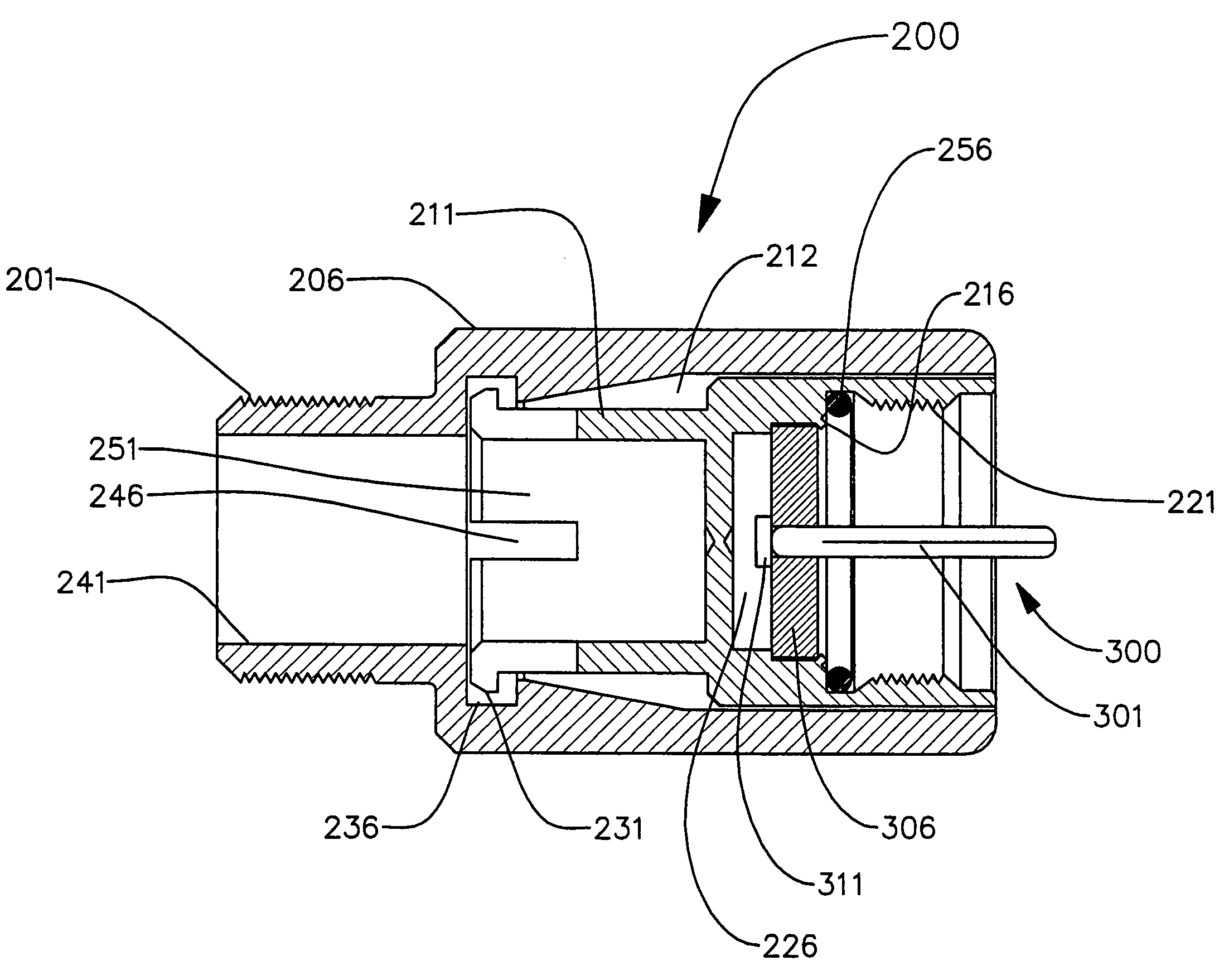
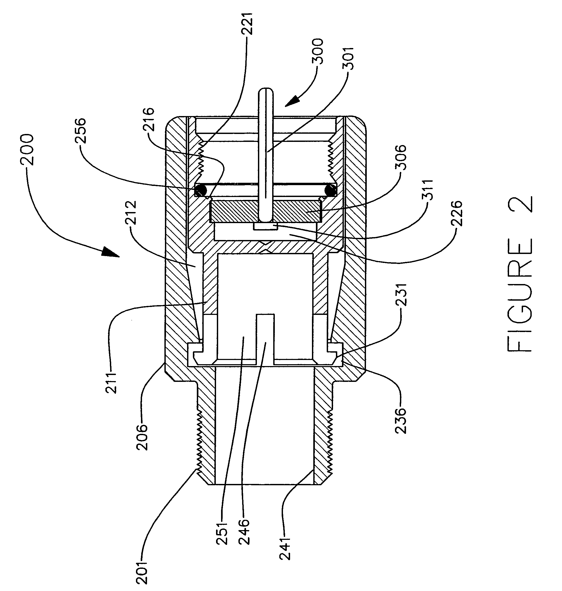
[0023]In preferred embodiments, the present invention can provide an RF terminator having a reduced number of components and a reduced length (thereby reducing the overall amount of material required and, hence, cost). In addition, reduced length can reduce cantilever forces that may be applied to an equipment port, which can provide a more robust, or less prone to breakage system. In preferred embodiments, the present invention may also provide an RF terminator that is highly tunable and contains a center conductor that emulates related cable while still providing ...


PUM


Abstract

An RF coaxial terminator includes an impedance match element mounted within a housing. The impedance match element includes a central conductive pin, a supportive element, and a resistor, wherein the resistor longitudinally extends in a direction that is not coaxial with the longitudinal axis of the central conductive pin.

Description

BACKGROUND OF THE INVENTION[0001]1. Field of the Invention[0002]The present invention relates generally to terminators and CATV coaxial connectors, and more particularly, to a terminator having an improved construction.[0003]2. Technical Background[0004]Cable transmission systems are in wide use throughout the world for transferring television signals, and other types of signals, between devices. For example, a typical CATV system utilizes coaxial cables to provide signal communication between a head end and distributed receiver sets. A conventional CATV system includes a permanently installed cable extending from the head end throughout the area to be served. Various devices, such as directional taps, are spaced along the cable. Individual subscribers are serviced by a drop cable connected to a selected terminal of an equipment box or other device. The terminals that extend from the equipment box are externally threaded female coaxial ports designed to receive a conventional F-conn...

Claims


Application Information

Patent Timeline
Patent Type & Authority Patents(United States)
IPC IPC(8): H01R9/05
CPCH01P1/266H01R24/44H01C1/01H01R2103/00
Inventor BURRIS, DONALD ANDREWLUTZ, WILLIAM BERNARD
Owner PPC BROADBAND INC
Why Eureka
Try Eureka