Coordination of electronic counter measures

a technology of electronic countermeasures and coordination, applied in the field of electronic warfare and electronic countermeasures, can solve problems such as false targets, and achieve the effect of improving vehicle chances, efficient and reliabl

Inactive Publication Date: 2009-02-10
SAAB AB
View PDF8 Cites 14 Cited by
  • Summary
  • Abstract
  • Description
  • Claims
  • Application Information

AI Technical Summary

Benefits of technology

[0007]It is therefore an object of the present invention to alleviate the above problem and thus provide an efficient and reliable solution for improving a vehicle's chances of evading any HOJ-based weapon systems.
[0010]According to a preferred embodiment of this aspect of the invention, the method involves specifying signal parameter information pertaining to a number of known threats; specifying a counter measure library containing a complete set of electronic warfare resources comprising any resources, which are included in at least one station of the group; and identifying, for each of said threats, at least one of the resources in the complete set of electronic warfare resources, which is estimated to constitute an appropriate counter measure to combat the threat. This procedure (which preferably performed before instigating a mission) is advantageous because thereby the chances of applying efficient counter measures in each given situation are highly improved.
[0012]According to yet another preferred embodiment of this aspect of the invention, the method involves specifying, in each station, for each electronic warfare resource included in this station whether the resource is currently available or not for emitting jamming signals; and repeatedly exchanging status messages with the other stations in the group. Each message here reflects a current availability of the electronic warfare resource included in the station from which the message is transmitted. The method also involves recording, based on any received status messages from the other stations in the group, a resource activation status for each resource of the electronic warfare resource included in the other stations in the group. Hence, all stations in the group remain updated with information regarding the usage of the electronic warfare resources in all the stations without a central control mechanism being required. Naturally, this vouches for flexible and reliable coordinated employment of the electronic warfare resources.
[0013]According to still another preferred embodiment of this aspect of the invention, each station in the group is associated with at least one threat warning system. The method involves determining in a first station in the group, based on an output from the at least one threat warning system and the resources activation statuses, whether at least one particular threat is appropriate to combat by means of a first electronic warfare resource in this station in coordination with at least one second electronic warfare resource in at least one second station in the group. If it is found that such a coordination is appropriate, a request message is transmitted from the first station to the at least one second station. Then, the first station waits for at least one reply message to be returned from the at least one second station in response to the request message. If at least one of any received reply messages indicates a service accept, a jamming signal is emitted from the first electronic warfare resource in coordination with a jamming signal emitted from each of the at least one second electronic warfare resource in the at least one second station, which has replied with a message that indicates a service accept. Thereby, coordinated signal emission from multiple stations may be accomplished entirely without the involvement of a central control mechanism. This, in turn, provides a very robust system.
[0015]According to yet another preferred embodiment of this aspect of the invention, the coordination of the usage of the at least one first and second resources involves determining an absolute point in time when the emission of the particular type of jamming signal shall begin. This coordination also involves determining a time synchronizing pattern for the emission of the particular type of jamming signal from the first electronic warfare resource and the at least one second electronic warfare resource. Hence, the desired illusion of a seemingly continuous signal transmission from a false signal source can be created. Moreover, by varying the time synchronizing pattern, so that a duty cycle of each electronic warfare resource is modified over time, the false signal source's position relative to the first and at least one second station may be altered.
[0018]According to another aspect of the invention this object is achieved by an electronic counter measures station for radiating jamming signals as described initially, wherein the communication unit is adapted to exchange the messages with at least one other electronic counter measures station, which is physically separated from the station and is associated with the station to form a group of stations. The messages include data pertaining to a usage of the at least one first electronic warfare resource and at least one corresponding second electronic warfare resource in at least one other electronic counter measures station in the group. The station also includes a resource handling unit adapted to, based on the messages and the time reference signal, coordinate the usage of the at least one first and second resources such that a particular type of jamming signal is emitted alternately either from the at least one first resource, or from the at least one second resource. The station is adapted to carry out this altering of the origin of the jamming signal essentially without any overlaps or gaps in time between the signals emitted from the different resources.

Problems solved by technology

Consequently, the jamming signals produce a false target, and any HOJ-based weapon fired towards the vehicles will most probably lock onto this false target, and therefore fail.

Method used


Image

  • Coordination of electronic counter measures
  • Coordination of electronic counter measures
  • Coordination of electronic counter measures

Examples


Embodiment Construction

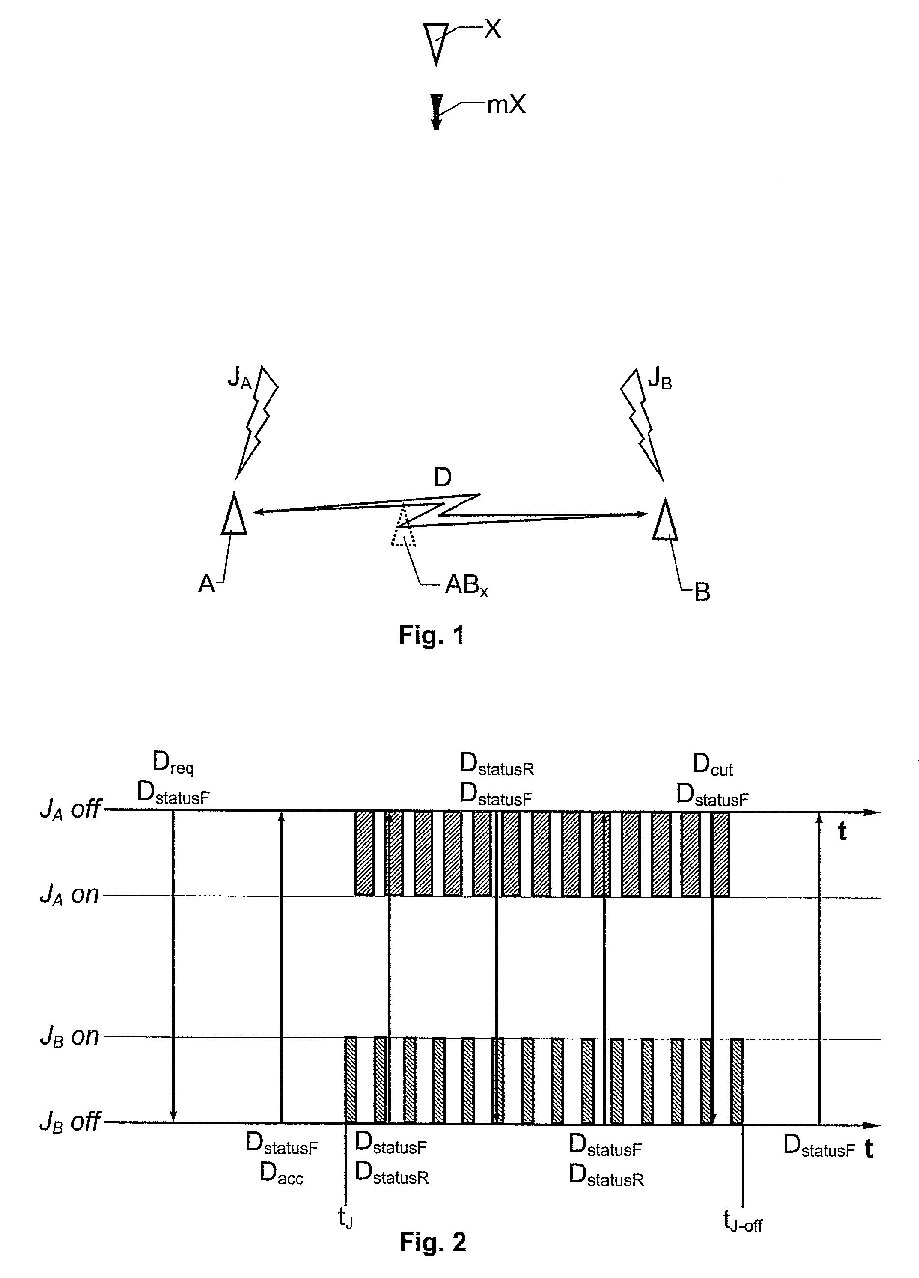
[0028]FIG. 1 shows two air vehicles A and B respectively, which each includes a proposed electronic counter measures station. It is presumed that a threat warning system of at least one of the vehicles A or B, say A, has registered a hostile air vehicle X, and / or a missile mX fired from this vehicle X. We further presume that each of the vehicles A and B is equipped with at least one electronic warfare resource, and that the vehicles A and B repeatedly exchange messages D indicating a current activation status of these resources.

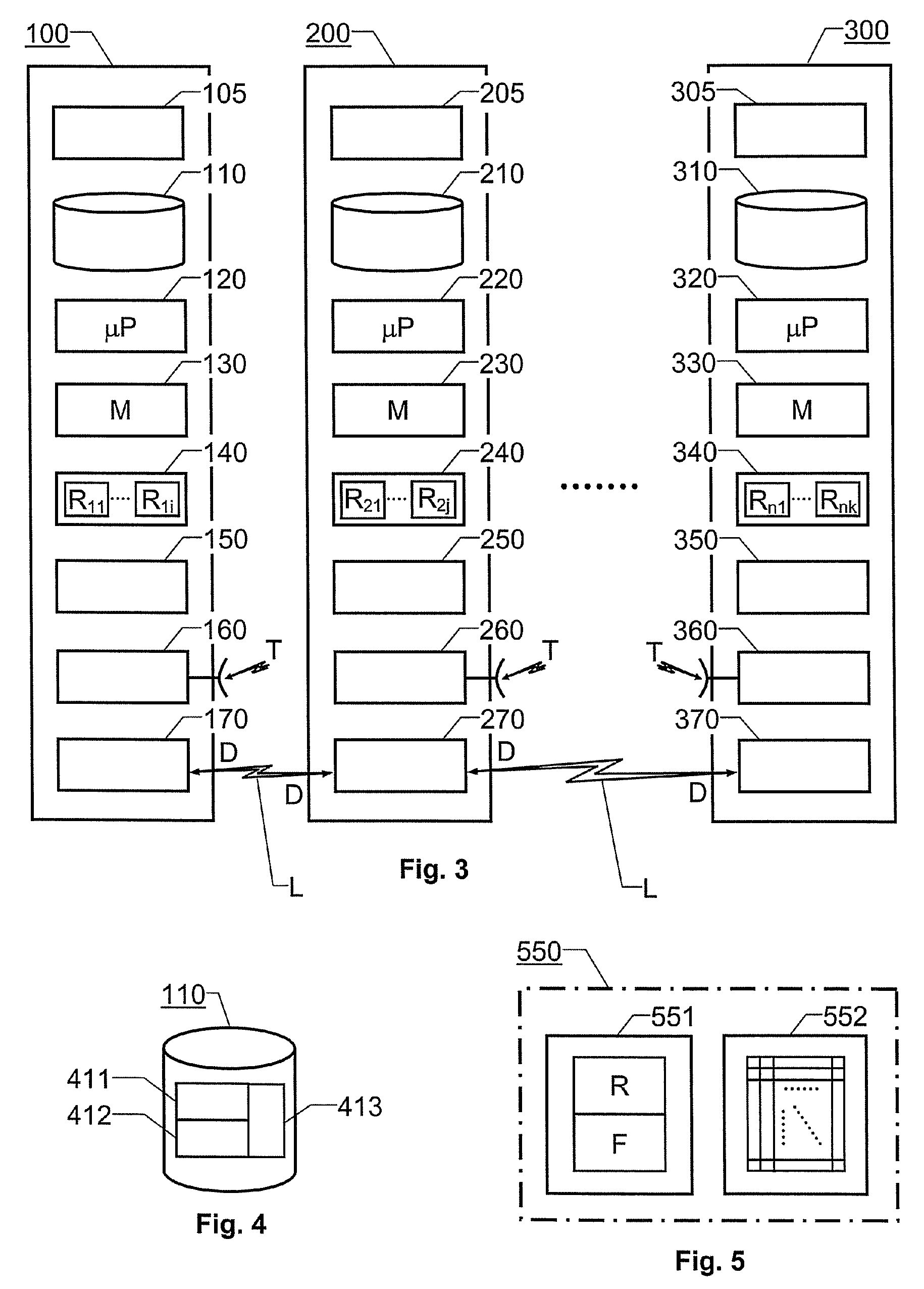
[0029]Moreover, each vehicle A and B is equipped with a database including a threat library, which specifies signal parameter information pertaining to a number of known threats. The database also includes a counter measure library, which specifies a complete set of electronic warfare resources that are carried either by the vehicle A, the vehicle B, or both vehicles. A table in the database, for each threat in the threat library, identifies at least one of ...


PUM


Abstract

An electronic counter measures solution. Jamming signals are emitted towards a threat to improve chances of survival for at least two vehicles, which are physically separated from one another, however associated with one another in a group. Each of the at least two vehicles receives a wireless time reference signal from an external resource. The vehicles exchange messages over a wireless data link. The messages pertain to usage of at least one electronic warfare resource in each vehicle. Based on the messages and the time reference signal the usage of at least one first electronic warfare resource in a first vehicle is coordinated with the usage of at least one second electronic warfare resource in a second vehicle, such that a particular type of jamming signal is emitted alternately either from the at least one first resource or from the at least one second resource, essentially without any overlaps or gaps in time. Thereby, a false target is created between the vehicles with respect to a weapon which operates in a so-called Home-on-Jam mode.

Description

CROSS-REFERENCE TO RELATED APPLICATIONS[0001]This application claims priority to European patent application 05001071.9 filed Jan. 20, 2005.FIELD OF THE INVENTION[0002]The present invention relates generally to electronic warfare and electronic counter measures. More particularly the invention relates to a method of producing jamming signals and electronic counter measures stations.BACKGROUND OF THE INVENTION[0003]Electronic warfare systems play an increasingly important role in modern battle scenarios. Tactical electronic warfare assets are therefore included in almost every new military land, sea or air vehicle. These assets may primarily be used for the purposes of self-protection (i.e. jamming an enemy weapon and / or vehicle to decrease the quality of any measurements performed by this weapon and / or vehicle, and thereby improve the chances of own survival), or for the purposes of generating a background noise intended to improve the protection of the vehicle itself, or other vehi...

Claims


Application Information

Patent Timeline
Patent Type & Authority Patents(United States)
IPC IPC(8): G01S7/38
CPCG01S7/38H04K3/65H04K2203/22H04K2203/36H04K3/825H04K2203/24H04K2203/34
Inventor FERM, NIKLASLINDVALL, THOMAS
Owner SAAB AB
Why Eureka
Try Eureka