Determining the location of the tip of an electronic stylus

a technology of electronic stylus and location, applied in the field of electronic stylus, can solve the problems of limiting the usefulness of remote locations, too large and/or heavy to be used in remote locations, and the size of laptop computers is simply overkill

Inactive Publication Date: 2009-02-10
MICROSOFT TECH LICENSING LLC
View PDF5 Cites 96 Cited by
  • Summary
  • Abstract
  • Description
  • Claims
  • Application Information

AI Technical Summary

Benefits of technology

[0010]Described herein are embodiments of various systems and methods for accurately determining the location of the tip of an electronic stylus. In accordance with one embodiment, an electronic stylus system includes an electronic stylus and base receiving unit. The electronic stylus includes two or more ultrasonic transmitters, an electromagnetic transmitter, and a writing tip. The base receiver unit includes two or more ultrasonic receivers and an electromagnetic receiver. The ultrasonic receivers of the base unit are operable to receive signals transmitted by the ultrasonic transmitters of the electronic stylus. Similarly, the electromagnetic receiver of the base unit is operable to receive signals transmitted by the electromagnetic transmitter of the stylus.

Problems solved by technology

Although laptop computers are quite useful in appropriate situations, they are often either too large and / or too heavy to be used in remote locations, or where space is limited.
Furthermore, battery life in laptop computers is typically only about 2-4 hours, further limiting their usefulness in remote locations.
Finally, laptop computers may simply be overkill in situations where data entry is all that is required.
Unfortunately, the screens on most PDAs are relatively small, thus limiting the amount of text or data that can be entered and viewed at once.
Unfortunately, these “camera based” digital pens have a number of drawbacks.
The most significant of these drawbacks is the fact that special “dotted” paper must be used for the pen to function.
This special paper is more expensive than standard paper.
Additionally, this special paper is often not readily available.
Unfortunately, these ultrasonic type digital pens are not very accurate in determining the precise location of the pen tip during writing and drawing.
However, when the pen is tilted the transmitter will no longer be aligned directly over the pen tip.
Since the receiver records the position of the transmitter, rather than the location of the pen tip, an inaccurate tip location will be recorded whenever the pen is tilted, which occurs naturally during writing.

Method used


Image

  • Determining the location of the tip of an electronic stylus
  • Determining the location of the tip of an electronic stylus
  • Determining the location of the tip of an electronic stylus

Examples


Embodiment Construction

[0021]The following description sets forth specific embodiments of an electronic stylus system and method that incorporates elements recited in the appended claims. The embodiment is described with specificity in order to meet statutory requirements. However, the description itself is not intended to limit the scope of this patent. Rather, the inventors have contemplated that the claimed invention might also be embodied in other ways, to include different elements or combinations of elements similar to the ones described in this document, in conjunction with other present or future technologies.

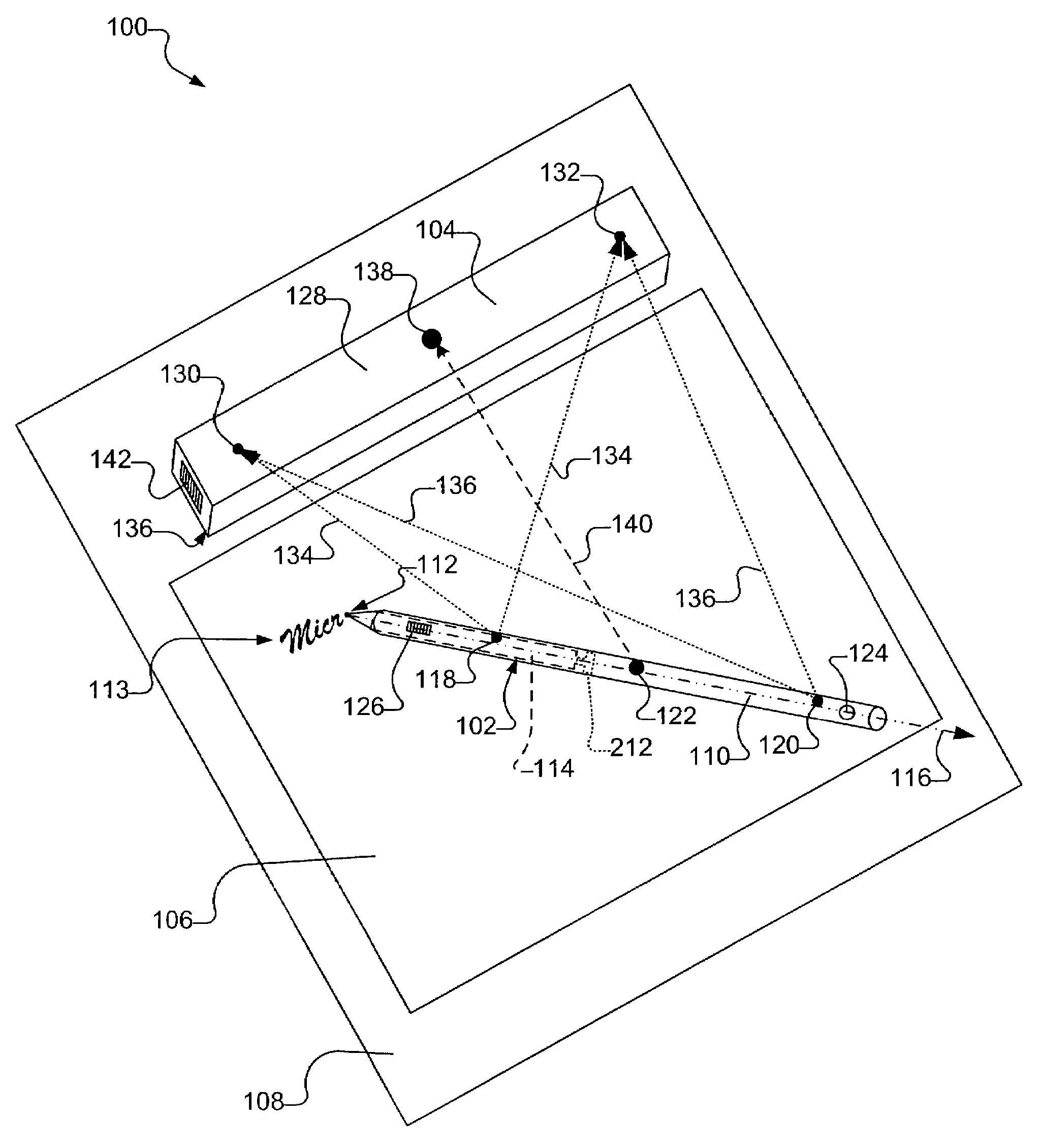
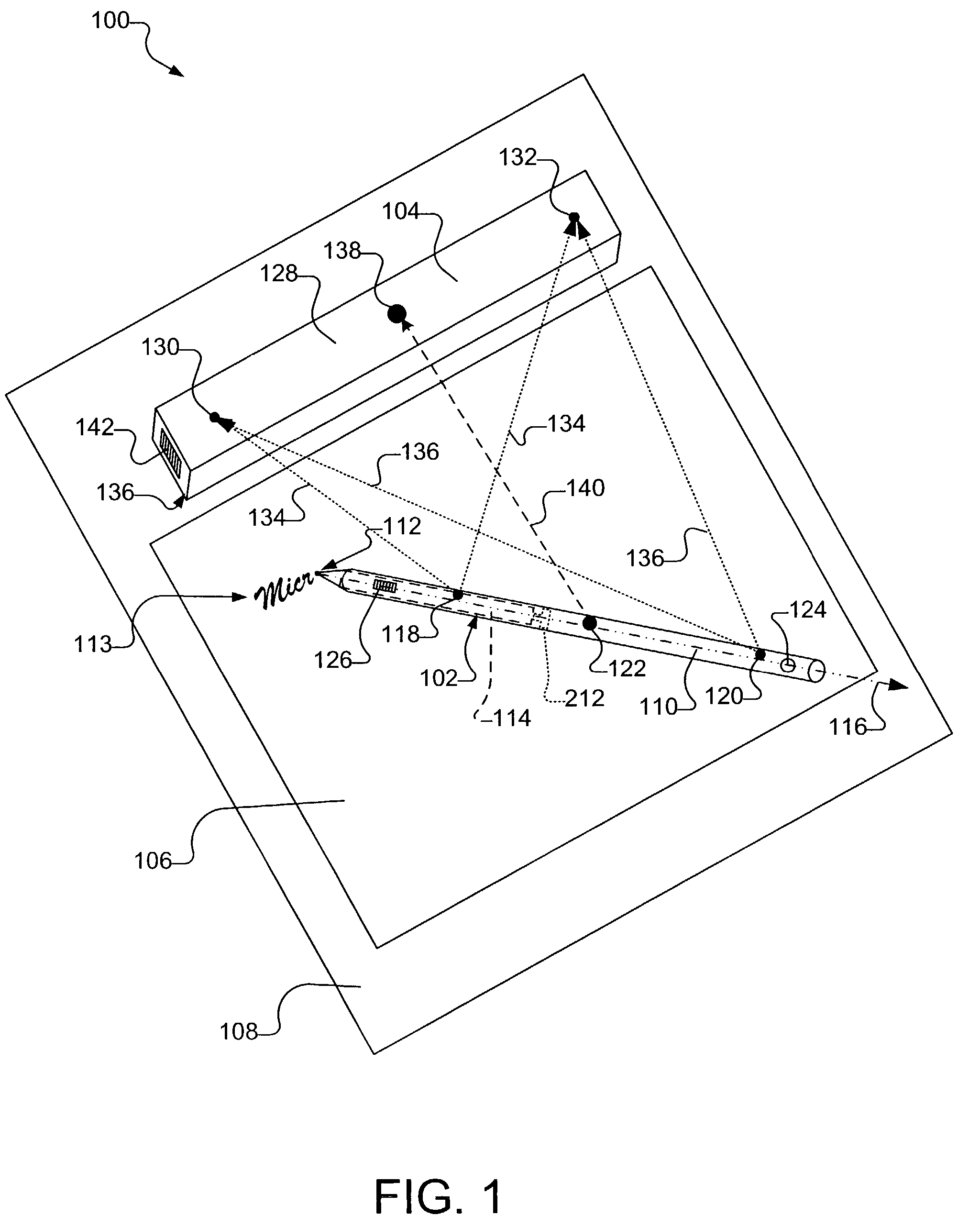
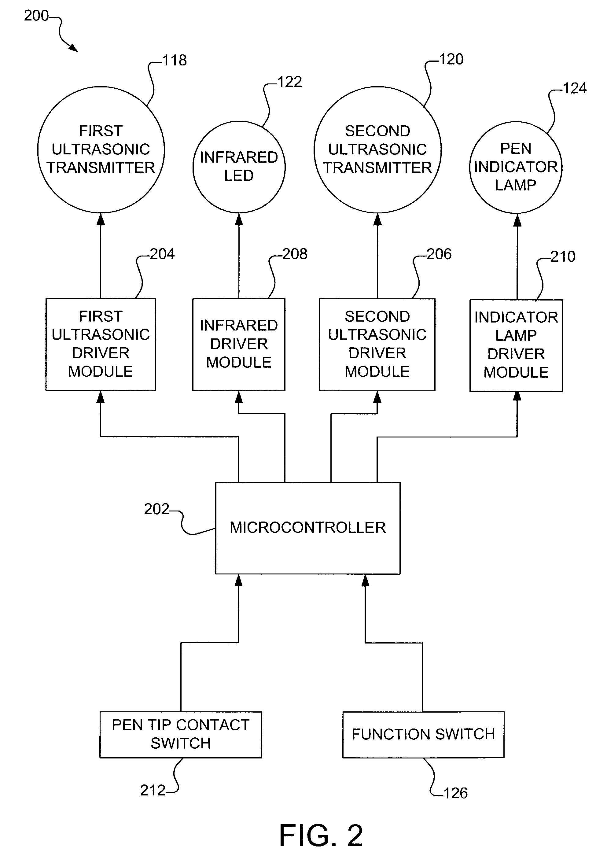
[0022]In general, the described embodiments relate to systems and methods for accurately capturing and recording the location of the tip of a stylus while the stylus is being used for writing or drawing on conventional writing paper, or the like. In accordance with various embodiments described herein, the stylus, referred to herein as the electronic stylus, includes at least two ultrasonic t...


PUM


Abstract

An electronic stylus system includes an electronic stylus and base receiving unit. The electronic stylus includes a first ultrasonic transmitter, a second ultrasonic transmitter, an electromagnetic transmitter, and a writing tip. The base receiver unit includes a first ultrasonic receiver, a second ultrasonic receiver, and an electromagnetic receiver. The ultrasonic receivers of the base unit are operable to receive signals transmitted by the ultrasonic transmitters of the electronic stylus. Similarly, the electromagnetic receiver of the base unit is operable to receive signals transmitted by the electromagnetic transmitter of the stylus. The location of the tip of the electronic stylus relative to a given reference point is determined using the locations of two ultrasonic transmitters relative to the two ultrasonic receivers.

Description

TECHNICAL FIELD[0001]The field of the invention relates generally to electronic styli, and more particularly to systems and methods for accurately locating and recording the position of the tip of an electronic stylus while the electronic stylus is in use.BACKGROUND[0002]Laptop computers are becoming increasingly popular for use by people who must travel or work in locations where desktop computers are not available or practical. Today's laptops are often just as powerful and feature-rich as many desktops. For example, many laptops now come equipped with large displays and full size keyboards. Although laptop computers are quite useful in appropriate situations, they are often either too large and / or too heavy to be used in remote locations, or where space is limited. Furthermore, battery life in laptop computers is typically only about 2-4 hours, further limiting their usefulness in remote locations. Finally, laptop computers may simply be overkill in situations where data entry is...

Claims


Application Information

Patent Timeline
Patent Type & Authority Patents(United States)
IPC IPC(8): G09G5/00B43L1/04G01S5/22G06F3/033G06F3/041G06F3/043G08C21/00
CPCG06F3/03545G06F3/043B66F17/00E04H6/42
Inventor BLAKE, ANDREWWILLIAMS, LYNDSAYSRINIVASAN, JAMESVABLAIS, WILLIAM
Owner MICROSOFT TECH LICENSING LLC
Why Eureka
Try Eureka