
Image-forming apparatus, process cartridge and image-forming method

a technology of image-forming apparatus and process cartridge, which is applied in the direction of electrographic process apparatus, instruments, developers, etc., can solve the problems of unstable charge amount of toner, image degradation, and complicated control, and achieve stable image

Active Publication Date: 2009-02-10
RICOH KK
View PDF96 Cites 2 Cited by
  • Summary
  • Abstract
  • Description
  • Claims
  • Application Information

AI Technical Summary

Benefits of technology

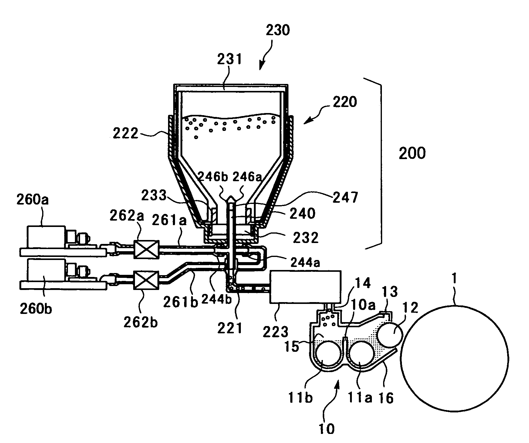
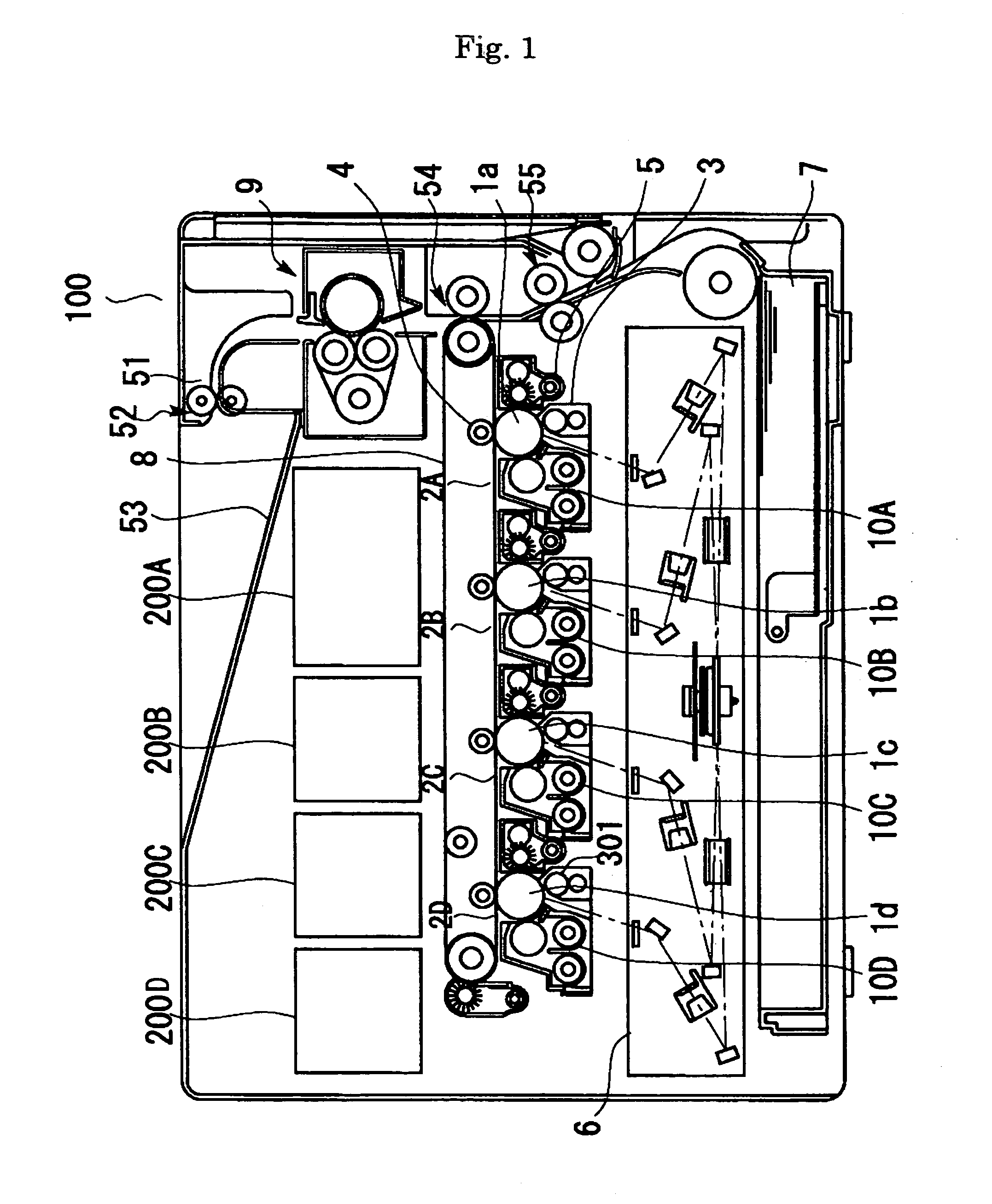
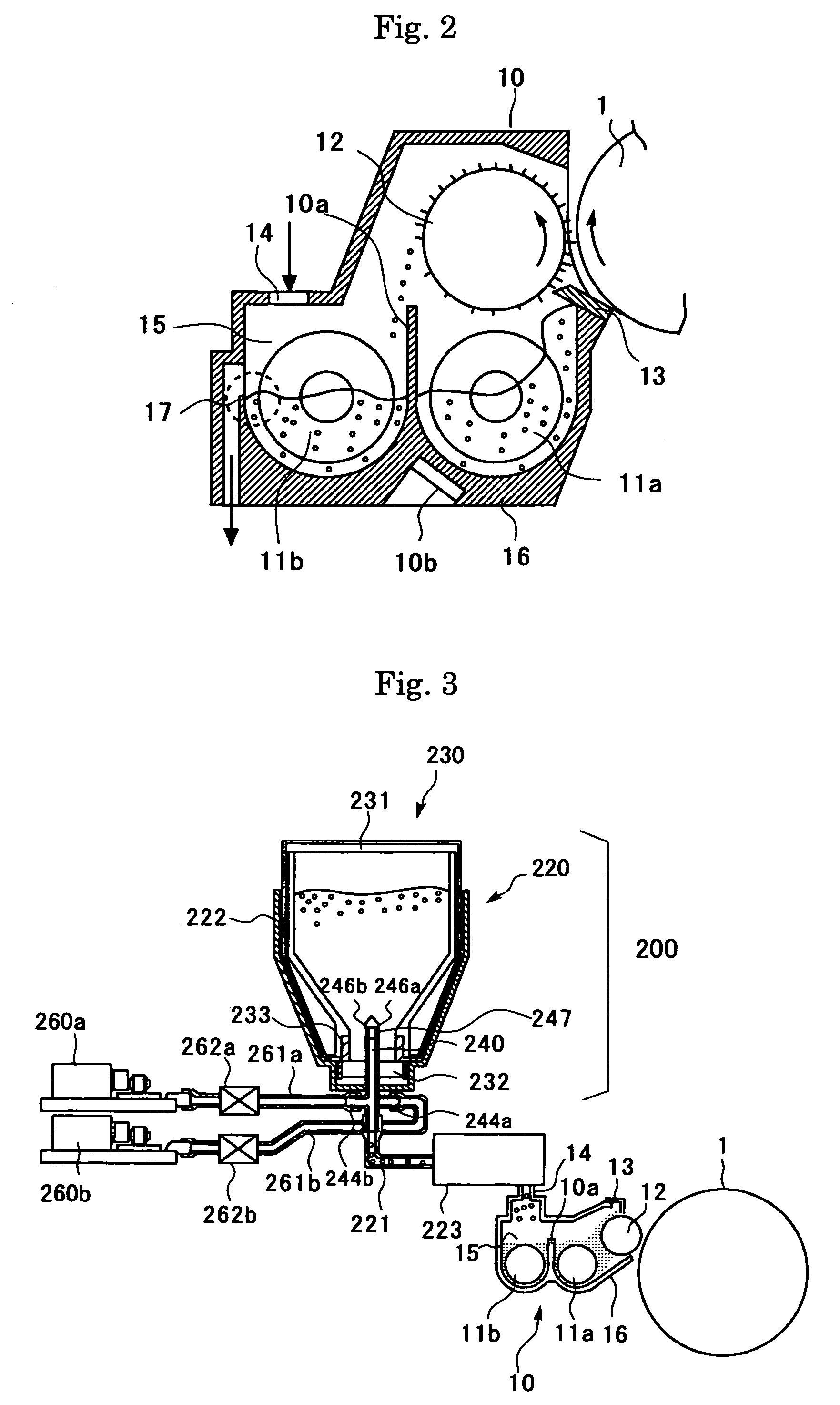
The present invention provides an image-forming apparatus, process cartridge, and image-forming method that can maintain uniform charge properties of the toner in the developing device and produce a stable image for a long period of time. The image-forming apparatus includes an image bearing member, a latent electrostatic image forming unit, and a developing unit with an image developing unit and a developer container. The mass abundance ratio of toner to carrier in the developer container is controlled at 80:20 to 95:5. The developer container includes a flexible pouched member and a developer outlet to discharge the developer. The developer satisfies a specific formula. The process cartridge contains an image bearing member and at least an image developing unit. The image-forming method involves forming a latent electrostatic image, developing it with the developer, transferring it onto a recording medium, and fixing it. The mass abundance ratio of toner to carrier in the developer container is controlled at 80:20 to 95:5. The developer container includes a flexible pouched member and a developer outlet to discharge the developer. The developer satisfies a specific formula.

Problems solved by technology

If the ratio of the degraded carrier increases in the developer container, the charge amount of the toner will be unstable, and troubles occur, for example, image degradation is induced.
Among these developer supplying systems, in case of the former, there is a problem that the developer must be supplied after the mix ratio between the toner and the carrier is adjusted, thus the control is complicated.
However, in the latter system, a big difference in specific gravity between the toner and the carrier leads to the state that each of them tends to exist disproportionately when both are mixed and filled in the developer supplying device.
If the supplying ratio of the toner and the carrier fluctuates, the charge amount of the carrier is variable in the developing device, and then the problem occurs that the stable developing property cannot be obtained.
However, in case that the developer is stirred and mixed in the supplying device, the carrier deteriorates before supplied to the developing device.
Therefore, it fails to obtain sufficiently the effect of trickle developing system that is the developing properties of the two-component developer can be constantly maintained by supplying the carrier before deterioration to the developing device.
When the property of the flowability differs largely between the toner and the carrier, the supplying property between them differs largely and the problem occurs that the stable charge amount of the toner cannot be obtained in the developing device.

Method used


Image

  • Image-forming apparatus, process cartridge and image-forming method
  • Image-forming apparatus, process cartridge and image-forming method
  • Image-forming apparatus, process cartridge and image-forming method

Examples


example 2

of Carrier Preparation

[0304]

silicone resin solution [solid content 23 mass % (SR2410:100 parts by Dow Corning Toray Silicone Co., Ltd.)]aminosilane [solid content 100 mass % (SH6020: by Dow0.6 parts Corning Toray Silicone Co., Ltd.)]toluene60 partsbutyl cellosolve60 parts

[0305]The above components were dispersed with a homomixer for 10 minutes, then a coat film forming solution of silicone resin was obtained.

[0306]By using calcinated ferrite powder [(MgO)1.8(MnO)49.5(Fe2O3)48.0: average particle diameter; 35 μm] as a core, the above coat film forming solution was coated to be a thickness of 0.15 μm on the surface of the core by a Spiller Coater (by Okada Seiko Co., Ltd.), and dried. The obtained carrier was baked by leaving to stand in an electric furnace at 160° C. for 1 hour. After cooling, the ferrite powder bulk was grinded and sieved with a sieve of 106 μm mesh, thereby obtained “Carrier 2”.

[0307]The thickness of the coat film was measured in the way that the film coating the s...

example 3

of Carrier Preparation

[0308]

acrylic resin solution (solid content 50 mass %)11.0 partsguanamine solution (solid content 70 mass %) 3.4 partstitanium oxide particles [average particle diameter 0.2 μm, 6.5 partsresistivity 1010 (Ω· cm)]silicone resin solution [solid content 23 mass % (SR2410:35.0 partsby Dow Corning Toray Silicone Co., Ltd.)]aminosilane [solid content 100 mass % (SH6020: by Dow 0.2 partsCorning Toray Silicone Co., Ltd.)]toluene 150 partsbutyl cellosolve 150 parts

[0309]The above component substances were dispersed with a homomixer for 10 minutes, then a blend coating film forming solution of acrylic resin and silicone resin containing alumina particles was obtained.

[0310]By using calcinated ferrite powder [(MgO)1.5(MnO)49.5(Fe2O3)48.5: average particle diameter; 65 μm] as a core, the above coat film forming solution was coated to be a thickness of 0.09 μm on the surface of the core by a Spiller Coater (by Okada Seiko Co., Ltd.), and dried. The obtained carrier was bake...

example 4

of Carrier Preparation

[0311]

acrylic resin solution (solid content 50 mass %)13.0 partsguanamine solution (solid content 70 mass %) 4.0 partstitanium oxide particles [average particle diameter 0.2 μm, 7.2 partsresistivity 1010 (Ω· cm)]silicone resin solution [solid content 23 mass % (SR2410:40.0 partsby Dow Corning Toray Silicone Co., Ltd.)]animosilane [solid content 100 mass % (SH6020: by Dow 0.3 partsCorning Toray Silicone Co., Ltd.)]toluene 180 partsbutyl cellosolve 180 parts

[0312]The above components were dispersed with a homomixer for 10 minutes, then a blend coating film forming solution of acrylic resin and silicone resin containing alumina particles was obtained.

[0313]By using calcinated ferrite powder [(MgO)1.5(MnO)49.5(Fe2O3)48.5: average particle diameter; 50 μm] as a core, the above coat film forming solution was coated to be a thickness of 0.10 μm on the surface of the core by a Spiller Coater (by Okada Seiko Co., Ltd.), and dried. The obtained carrier was baked by leavi...


PUM


Abstract

The present invention provides an image-forming apparatus containing an image bearing member, a latent electrostatic image forming unit, a developing unit, in which the developing unit contains an image developing unit, a developer supplying unit, and a developer container, the mass abundance ratio of the toner to the carrier is 80:20 to 95:5 in the developer container, the developer container contains a flexible pouched member which reduces its volume by reducing the internal pressure and a developer outlet to discharge the developer contained therein, the developer satisfies a relation of formula (1) where A denotes a percentage of voids calculated from a tap density of the toner and B denotes a degree of fluidity (sec / 50g) of the developer at a toner coverage ratio of the carrier being 50%:A≦0.01×B−0.2  (1).

Description

BACKGROUND OF THE INVENTION[0001]1. Field of the Invention[0002]The present invention relates to an image-forming apparatus such as copiers, facsimiles and printers, in which an image is formed by electrostatic copying process, a process cartridge which is provided in the image-forming apparatus, and an image-forming method which is used for the image-forming apparatus.[0003]2. Description of the Related Art[0004]The method for visualizing image information via latent electrostatic images, for example, electrophotography is now used in various fields. In electrophotography, a latent electrostatic image is formed on a photoconductor by charging and exposing, the image is developed with a developer containing toner, and visualized via transferring and fixing. The developers used herein are a two-component developer consisting of a carrier and a toner, and one-component developer consisting of a toner alone such as magnetic toner. The two-component developers have advantages of good co...

Claims


Application Information

Patent Timeline
Patent Type & Authority Patents(United States)
IPC IPC(8): G03G15/08
CPCG03G15/0874G03G15/0879G03G15/0877G03G2215/0609G03G2215/0682
Inventor TOMITA, MASAMI
Owner RICOH KK
Learn More