Variable speed refrigeration system

a refrigeration system and variable speed technology, applied in the field of refrigerators, can solve the problems of increasing the internal temperature of the refrigerator, low speed operation, medium speed operation, etc., and achieve the effects of reducing noise output, minimal thermal stratification, and energy saving

Inactive Publication Date: 2009-02-17
MAYTAG
View PDF63 Cites 16 Cited by
  • Summary
  • Abstract
  • Description
  • Claims
  • Application Information

AI Technical Summary

Benefits of technology

The present invention relates to a new type of refrigerator that has several benefits including being very energy-efficient, low in noise levels, and minimizing heat transfer between different parts of the fridge. This new refrigerator uses a special kind of cooling system called a variable speed refrigeration system which helps keep all its sections constantly cold without requiring too much electricity.

Problems solved by technology

The technical problem addressed by this patent is how to create a more efficient and effective refrigeration system for use in both commercial and home settings. Current systems struggle to achieve optimal performance due to limitations related to sensor technology, controller capabilities, and mechanical design. This patent proposes a new approach that integrates multiple components operating at their best levels to optimize energy usage and cooling effects.

Method used


Image

  • Variable speed refrigeration system
  • Variable speed refrigeration system
  • Variable speed refrigeration system

Examples


Embodiment Construction

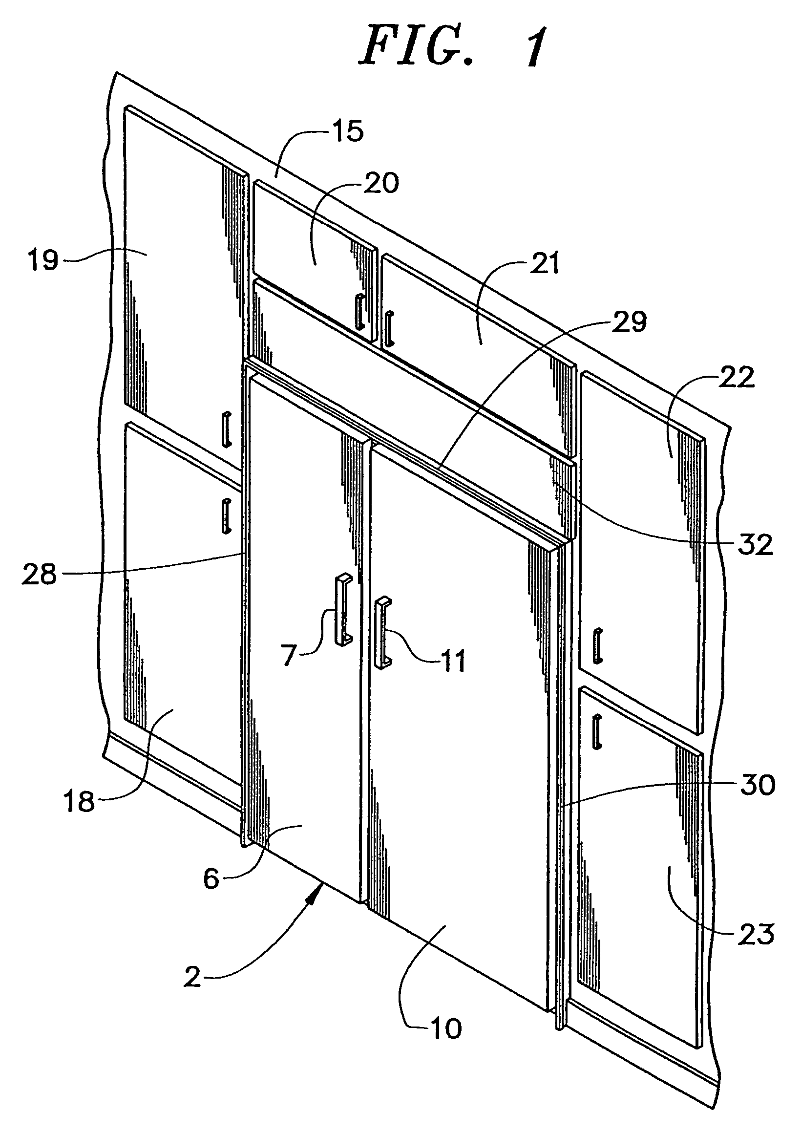
[0018]With initial reference to FIG. 1, a refrigerator constructed in accordance with the present invention is generally shown at 2. Refrigerator 2 is shown to include a freezer door 6 having an associated handle 7 and a fresh food door 10 having an associated handle 11. In the embodiment shown, refrigerator 2 is of the recessed type such that, essentially, only freezer and fresh food doors 6 and 10 project forward of a wall 15. The remainder of refrigerator 2 is recessed within wall 15 in a manner similar to a plurality of surrounding cabinets generally indicated at 18-23. Refrigerator 2 also includes a plurality of peripheral trim pieces 28-30 to blend refrigerator 2 with cabinets 18-23. One preferred embodiment employs trim pieces 28-30 as set forth in pending U.S. patent application Ser. No. 10 / 385,607 entitled “Fastening System for Appliance Cabinet Assembly” filed on Mar. 12, 2003 and which is incorporated herein by reference. Finally, as will be described more fully below, re...


PUM


Abstract

A refrigerator incorporates a variable speed refrigeration system including a variable speed compressor, a variable speed evaporator fan, a variable speed fresh food compartment stirring fan and a variable position damper. Various temperature sensors are provided to sense system parameters which are used by a controller to regulate each of the variable components in order to compensate for temperature changes within at least one refrigerator compartment in a highly effective, energy efficient and synergistic manner.

Description


Claims


Application Information

Patent Timeline
Owner MAYTAG
Why Eureka
Try Eureka