
Method and apparatus for acquiring noise reduced high frequency signals

Active Publication Date: 2014-06-24
SUMITOMO SHI CRYOGENICS OF AMERICA
View PDF2 Cites 4 Cited by
  • Summary
  • Abstract
  • Description
  • Claims
  • Application Information

AI Technical Summary

Benefits of technology

This patent describes a method for reducing noise in output signals from an electrical device called a capacitance diaphragm gauge (CDG) or transducer that measures a parameter, such as pressure or humidity. The method involves amplifying the output signal, converting it to digital samples, and averaging them over two time segments to create a final signal with reduced noise. This results in an output signal that more accurately represents the parameter applied to the device. The method can be used with different CDG or transducer models and has improved accuracy compared to previous methods.

Problems solved by technology

The accuracy of the measurement of pressure by a CDG can be negatively impacted by several factors, one of which is the signal noise within the electronic circuits that convert the capacitance changes caused by movement of the diaphragm in response to pressure changes.
The signal noise may result from random noise that is often present in electronic systems and noise at spurious frequencies caused by other electronic systems in the proximity to the CDG sensor system.
Although such signal noises can be removed by digital or analog filters, the costs of implementing such filters may be prohibitive.
The costs include economic costs and physical costs (e.g., space requirements within enclosures).

Method used


Image

  • Method and apparatus for acquiring noise reduced high frequency signals
  • Method and apparatus for acquiring noise reduced high frequency signals
  • Method and apparatus for acquiring noise reduced high frequency signals

Examples


Embodiment Construction

[0022]The improvements to capacitance diaphragms are disclosed herein with respect to exemplary embodiments of a system and a method. The embodiments are disclosed for illustration of the system and the method and are not limiting except as defined in the appended claims. Although the following description is directed to a particular embodiment of a capacitance diaphragm gauge, it should be understood that the disclosed system and method can be applied to other embodiments of capacitance diaphragm gauges.

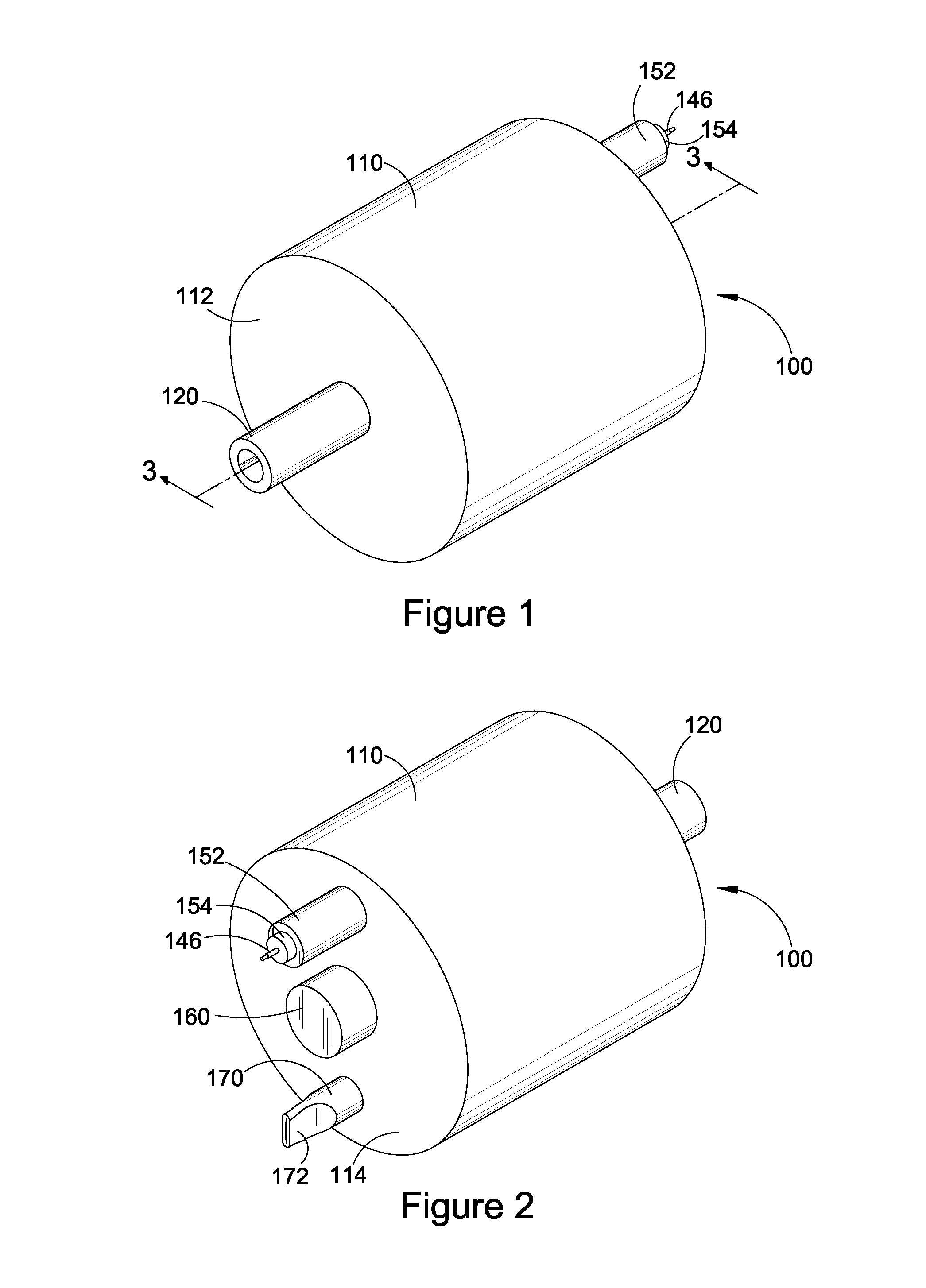
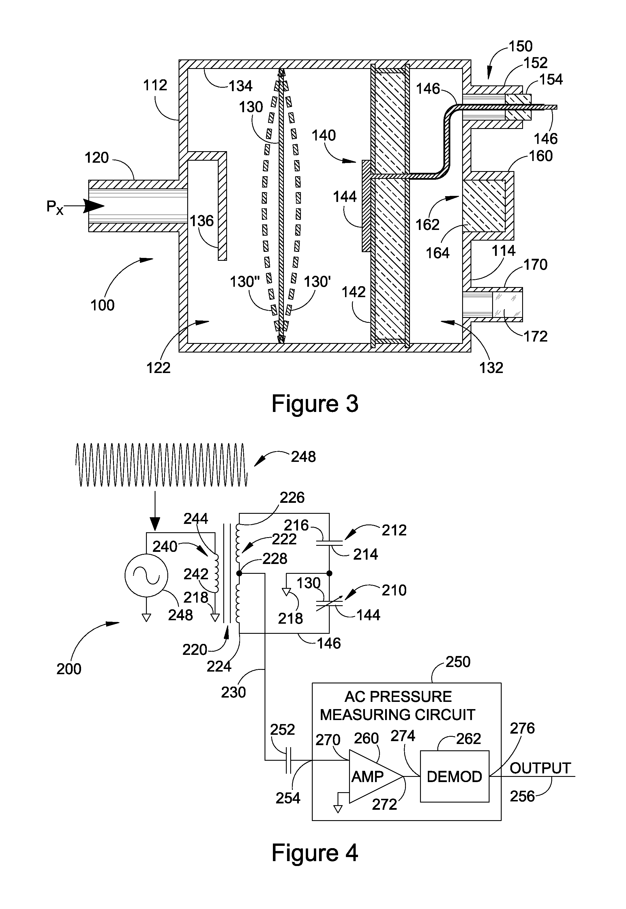
[0023]FIG. 1 illustrates a front perspective view of an exemplary capacitance diaphragm gauge (CDG) 100, which is installable into a pneumatic system (not shown) to measure the pressure within the system. In particular, the CDG is used to measure very low pressures resulting from evacuation of the pneumatic system. FIG. 2 illustrates a rear perspective view of the CDG of FIG. 1 which is rotated 180° from the view in FIG. 1. FIG. 3 illustrates a cross-sectional view of the CDG taken ...


PUM


Abstract

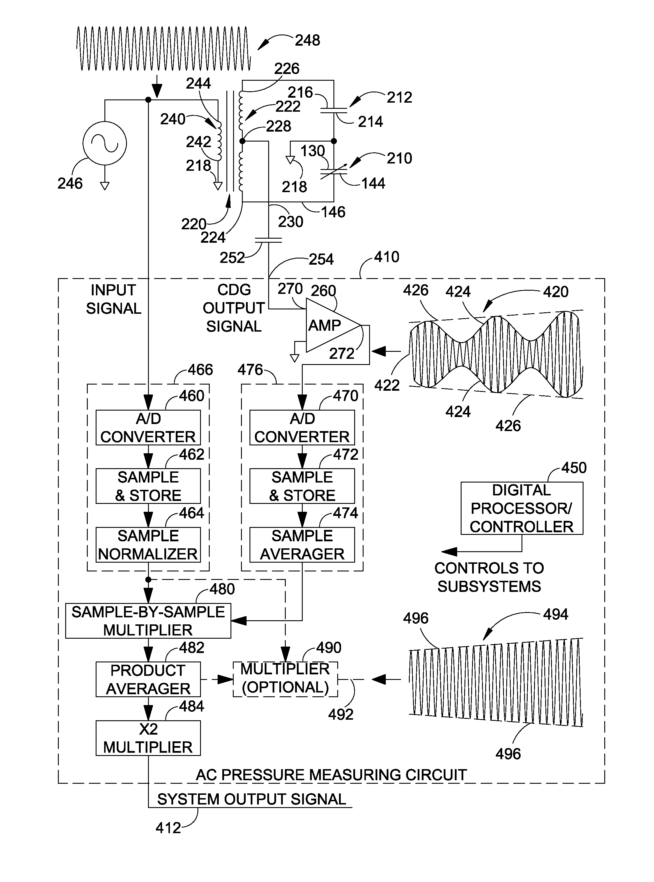
A system and method receive the output signal from a capacitance diaphragm gauge (CDG) and generate a noise reduced output signal. An input signal processing circuit receives an input signal from a signal source that drives the CDG. The input signal processing circuit generates a segment of N normalized digital samples of the input signal. An output signal processing circuit receives the output signal from the CDG and generates M segments of N digital samples of the CDG output signal and averages the corresponding samples in the M segments to generate a signal segment of N averaged samples. Each of the N averaged samples is multiplied by a corresponding one of the N normalized samples to generate N products. The N products are averaged to generate an average product, which is multiplied by a constant to generate a system output signal with reduced noise.

Description

RELATED APPLICATIONS[0001]The present application claims the benefit of priority under 35 USC §119(e) to U.S. Provisional Application No. 61 / 765,945 filed on Feb. 18, 2013, which is incorporated by reference herein.BACKGROUND OF THE INVENTION[0002]1. Field of the Invention[0003]The present invention is in the field of capacitance diaphragm gauges which measure pressure based on the deflection of a diaphragm.[0004]2. Description of the Related Art[0005]Absolute capacitance diaphragm gauges (CDGs) measure pressure by sensing the capacitance change associated with deflection of a diaphragm whereby one side of the diaphragm (“the Px side”) is exposed to the pressure to be measured (Px) and the other side of the diaphragm is exposed to a sealed reference vacuum cavity in which an ultrahigh vacuum (e.g., less than 10−9 Torr) has been created prior to the sealing of the reference cavity.[0006]The CDG measures capacitance between a diaphragm and one or more fixed electrodes housed in the re...

Claims


Application Information

Patent Timeline
IPC IPC(8): H03B1/00
CPCH03B1/00H03K5/1252G01L9/0072G01L9/12
Inventor FERRAN, ROBERT, J.
Owner SUMITOMO SHI CRYOGENICS OF AMERICA
Learn More