Roof mounted wind turbine

a wind turbine and roof technology, applied in wind energy generation, motors, sustainable buildings, etc., can solve the problems of high installation cost, and achieve the effect of reducing the electricity cost of the domestic consumer and reducing the consumption of power

Inactive Publication Date: 2009-04-14
WINDSAVE HLDG
View PDF18 Cites 4 Cited by
  • Summary
  • Abstract
  • Description
  • Claims
  • Application Information

AI Technical Summary

Benefits of technology

[0015]Thus, it may be possible by means of the invention to reduce consumption of power from the national grid, which may lead to savings of other power sources, especially non-renewable sources. Furthermore, electricity costs for the domestic consumer can be reduced.

Problems solved by technology

That requires large-scale commercial wind farms but they are expensive to set up due to the high cost of the turbines required.

Method used


Image

  • Roof mounted wind turbine
  • Roof mounted wind turbine
  • Roof mounted wind turbine

Examples


Embodiment Construction

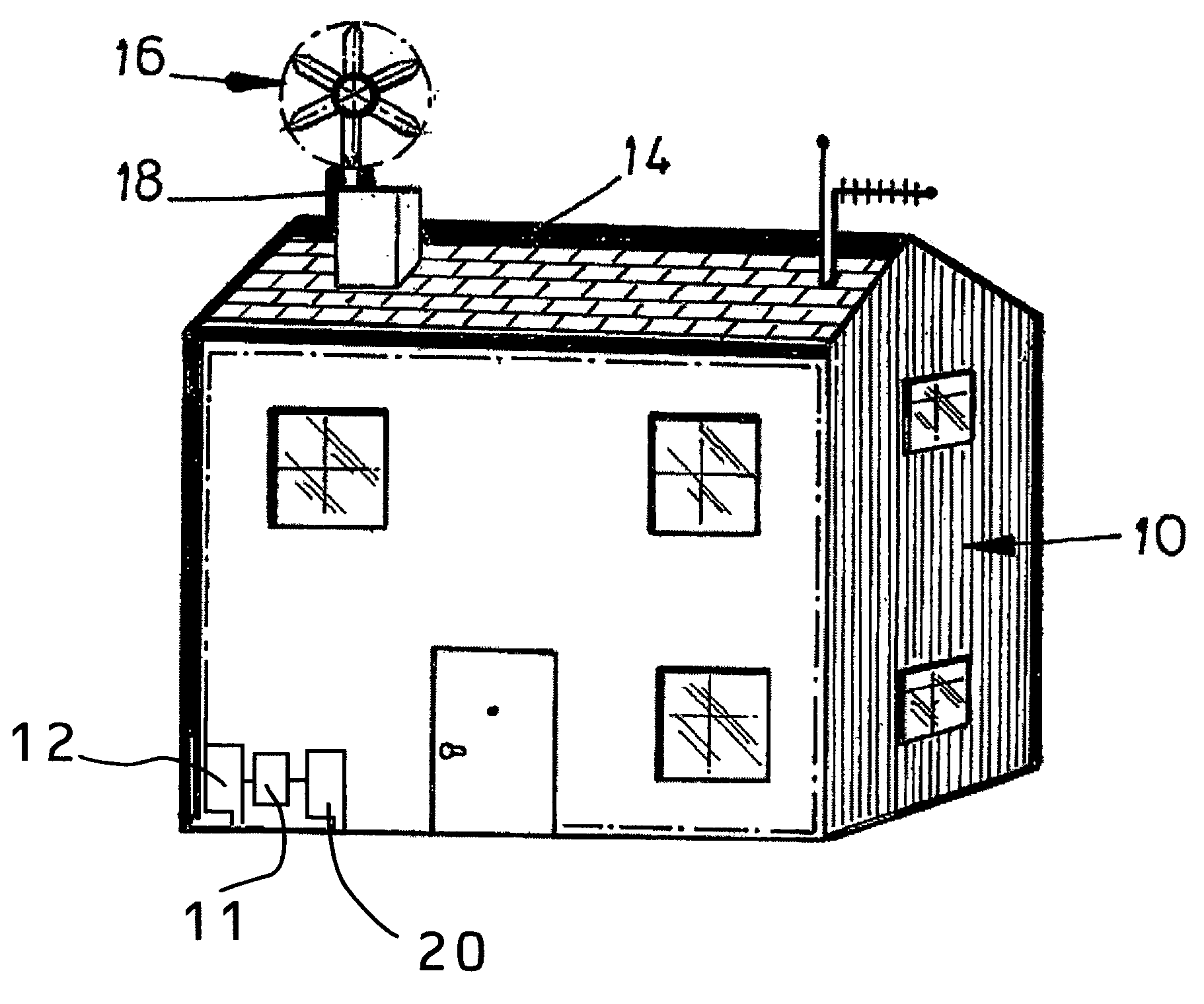
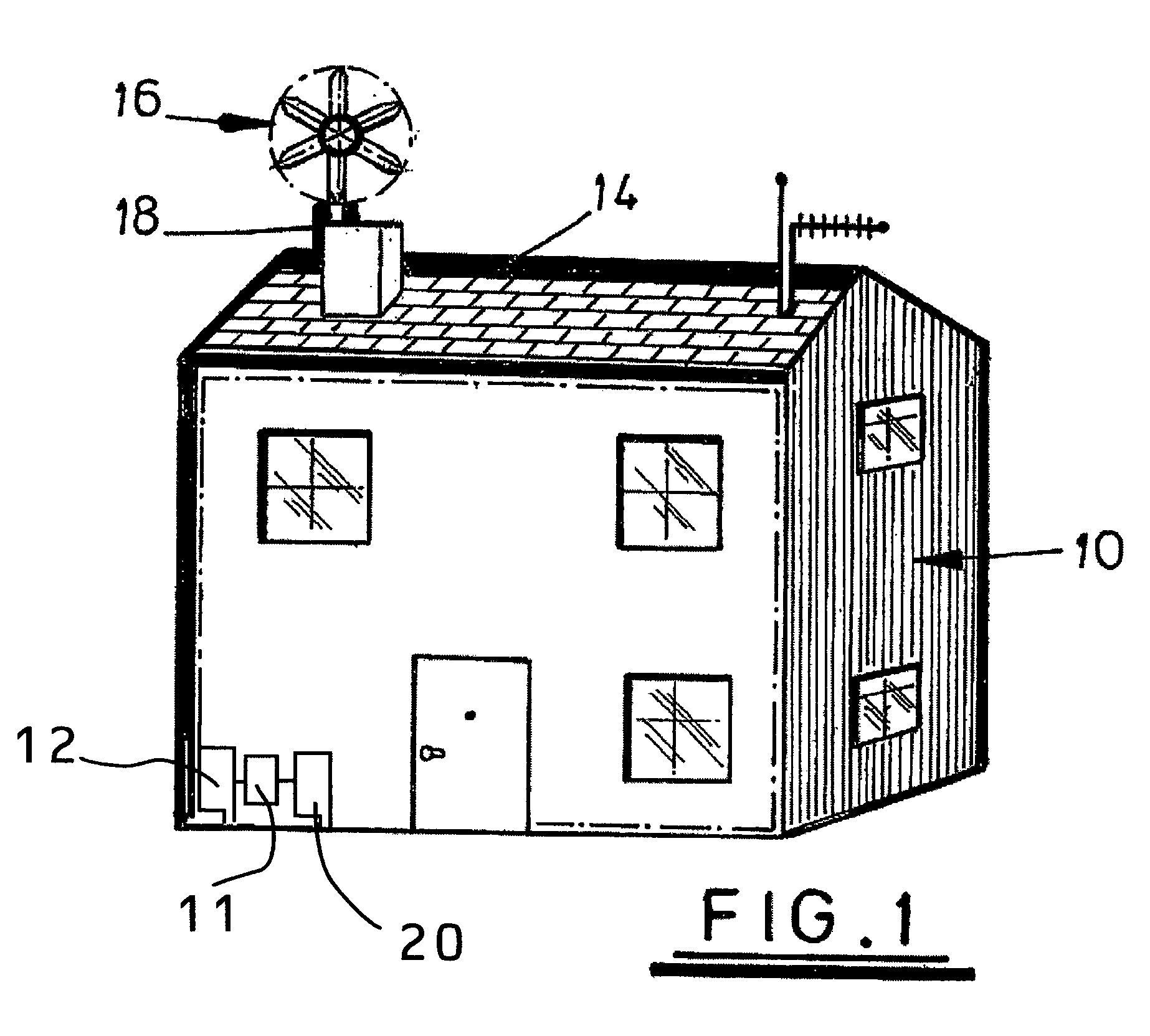
[0026]Referring to FIG. 1 of the accompanying drawings, a property 10, such as a house, has a mains electricity supply 12 from an external source, such as from the national grid facilitated by a utility company. Mounted on the roof 14 of the property 10 is a turbine 16, in the form of a wind vane. Only one wind vane is shown but equally a group of wind vanes may be used. The turbine is arranged to face the direction of the prevailing wind to cause the blades of the turbines to rotate. The rotation of the turbine is used to power an electricity generator 18. The electricity generated by the generator is fed to a unit 20 that is coupled to mains electricity junction box within the property. Also included is an interface 11, whereby switching between the secondary electricity supply and the power generated by the electricity generator can be achieved.

[0027]The unit 20 has switching therein, whereby the electicity from the generator is used for the property in preference to the external...


PUM


Abstract

A system for generating electrical power for an individual property (10) comprises a wind powered electricity generator (16) mounted on that property and arranged so that the electrical power generated be used in that property in preference to or to supplement electrical power provided by the national grid or other general electrical energy source.

Description

CROSS-REFERENCE TO RELATED APPLICATIONS[0001]This application claims priority to PCT / GB03 / 00442 filed Feb. 3, 2003 and Great Britain Patent Application Ser. No. 0202435.4, filed Feb. 2, 2002.FIELD OF THE INVENTION[0002]This invention concerns renewable energy resources.BACKGROUND OF THE INVENTION[0003]Wind energy has great potential as a renewable energy source. A recent report examining different renewable energy resources found that a total of 60 GW of cost effective renewable energy was available with the top two sources in terms potential being offshore wind (25 GW) and wave energy (14 GW). The next largest source of renewable energy is onshore wind (12 GW).[0004]Currently wind power is used to generate electrical energy for the national grid. That requires large-scale commercial wind farms but they are expensive to set up due to the high cost of the turbines required.SUMMARY OF THE INVENTION[0005]An object of this invention is to provide an improved means of utilising wind powe...

Claims


Application Information

Patent Timeline
Patent Type & Authority Patents(United States)
IPC IPC(8): F03D9/00H02P9/00F03D1/04F03D11/04
CPCF03D1/04F03D9/003F03D11/04F05B2220/7066F05B2220/7068F05B2240/911Y02B10/30Y02E10/725Y02E10/728F03D13/20F03D9/255F03D9/11F03D9/34Y02E10/72Y02E70/30
Inventor GORDON, DAVID HYMAN
Owner WINDSAVE HLDG
Why Eureka
Try Eureka