Steer valve with hydraulic vehicle position feedback

a technology of steering valve and position feedback, which is applied in the direction of fluid couplings, couplings, transportation and packaging, etc., can solve the problems of adding substantially to the size and cost of the controller, and achieve the effect of increasing the total flow ratio

Active Publication Date: 2009-02-17
DANFOSS AS
View PDF12 Cites 2 Cited by
  • Summary
  • Abstract
  • Description
  • Claims
  • Application Information

AI Technical Summary

Benefits of technology

[0006]Accordingly, it is an object of the present invention to provide an improved fluid controller for use in a vehicle steering system which can provide a substantially larger ratio of total flow to the fluid pressure actuated device to the flow through the fluid meter.

Problems solved by technology

Thus, the typical prior art fluid controller requires a relatively large displacement fluid meter when used in large “off highway” vehicles.
However, the use of large displacement fluid meters in the fluid controller adds substantially to the size and cost of the controller.

Method used


Image

  • Steer valve with hydraulic vehicle position feedback
  • Steer valve with hydraulic vehicle position feedback
  • Steer valve with hydraulic vehicle position feedback

Examples


Embodiment Construction

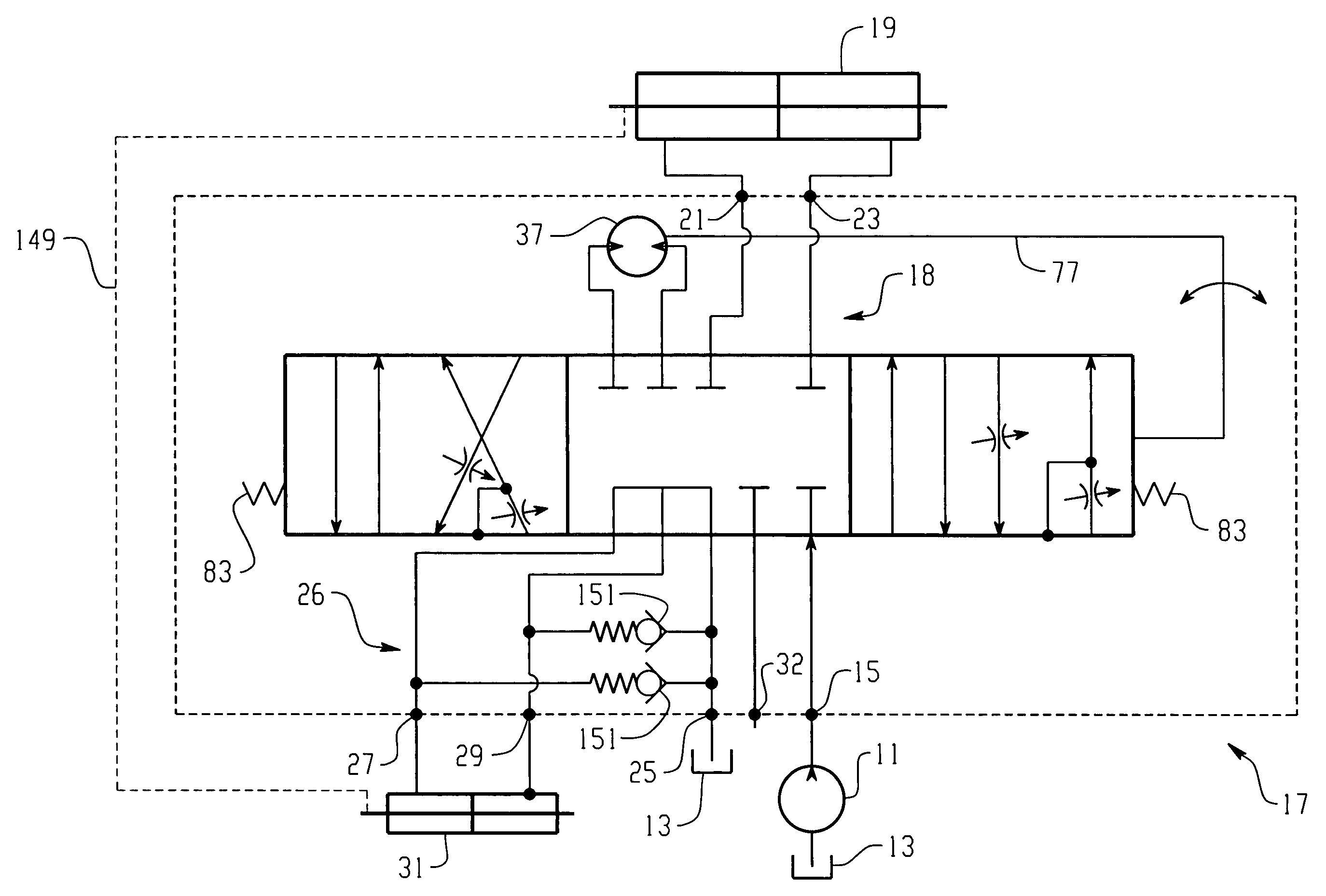
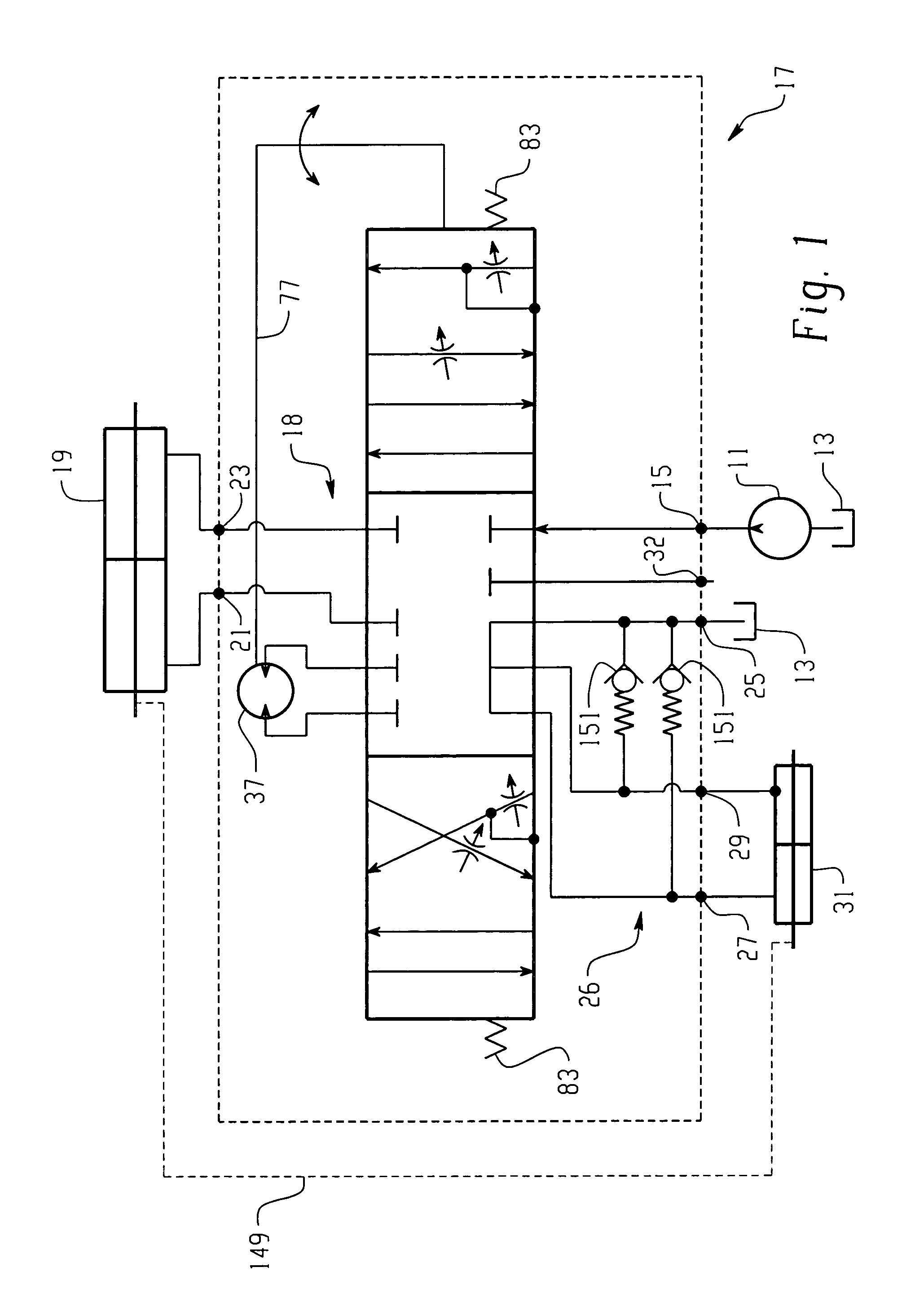
[0019]Referring now to the drawings, which are not intended to limit the invention, FIG. 1 is a hydraulic schematic of a vehicle hydrostatic steering system and a fluid controller made in accordance with the teachings of the present invention. The system includes a fluid pump 11, shown herein as a fixed displacement pump, having its inlet connected to a system reservoir 13. The outlet of the pump 11 is communicated to an inlet port 15 of a fluid controller, generally designated 17.

[0020]Referring still to FIG. 1, the fluid controller 17 controls a main fluid path, generally designated 18, from the pump 11 to a primary steering cylinder 19, or some other suitable fluid pressure operated steering actuator or device, all of which are within the scope of the invention. The fluid controller 17 includes a pair of primary control fluid ports 21 and 23, which are connected to the opposite ends of the steering cylinder 19, and a return port 25, which returns fluid to the reservoir 13. The fl...


PUM


Abstract

A fluid controller (17) controls a main fluid path (18) from a pump (11) to a primary steering cylinder (19) and a second fluid path (26) from a fluid meter (37) to a second cylinder (31). A mechanical or electrical linkage (149) couples the primary steering cylinder (19) to the second cylinder (31) such that displacement of the primary cylinder (19) results in proportional corresponding displacement of the second cylinder (31). The main fluid path (18) and the second fluid path (26) are maintained separate from each other. As such, the main fluid path (18) provides pressurized fluid from the pump to the primary steering cylinder (19) without communicating main fluid flow to the secondary cylinder (31). Due to the separate fluid paths, the present invention can be used to provide a substantial amount of fluid through a fluid controller (17) with a relatively small displacement fluid meter (37).

Description

BACKGROUND OF THE DISCLOSURE[0001]The present invention relates to fluid controllers of the type used to control the flow of fluid from a source of pressurized fluid to a fluid pressure actuated device, such as a steering cylinder.[0002]Although the present invention may be used with fluid controllers of many types, and having various constructions and applications, it is especially advantageous when used with a full-fluid-linked steering controller, for use on a vehicle of primarily the “off highway” type. Therefore, the present invention will be described in connection therewith.[0003]A typical prior art fluid controller and valving therefor is illustrated in U.S. Pat. No. 4,620,416, assigned to the assignee of the present invention and incorporated herein by reference. The typical prior art fluid controller of the type to which the present invention relates includes a housing which defines various fluid ports, and further includes a fluid meter, a valve means defining a main flui...

Claims


Application Information

Patent Timeline
Patent Type & Authority Patents(United States)
IPC IPC(8): B62D5/083B62D5/097
CPCB62D5/093B62D5/097Y10T137/86638Y10T137/86662
Inventor GEHLHOFF, WADE L.
Owner DANFOSS AS
Why Eureka
Try Eureka