Decreased skin shear device

a skin shear and skin technology, applied in the direction of wheelchairs/patient conveyances, movable seats, wheelchairs, etc., can solve the problems of high degree of shear force to the user, and achieve the effect of reducing the concern about shear force, and reducing the degree of skin shear

Inactive Publication Date: 2009-02-17
HOGG MARK G
View PDF17 Cites 13 Cited by
  • Summary
  • Abstract
  • Description
  • Claims
  • Application Information

AI Technical Summary

Benefits of technology

[0011]The present invention provides a means to eliminate and / or significantly decrease skin shear during the movement of a seated occupant by the use of a back slide plate and a seat slide plate. The purpose is to provide a means to which the user can be repositioned effectively and efficiently with significant decrease of concern about shear forces. All reclining devices (motion furniture) create movement that results in a high degree of shear force to the user. The present invention addresses this problem through the use of a device that moves in a corresponding fashion to that of the human anatomy. The device simply transfers shear force due to movement from slide plates that correspond to the user's anatomy to fixed plates. The slide plates follow the movement of the user's body during both expansion and contraction of the upper legs, hip, lower back, buttocks and back.
[0012]With the present invention, the mirroring effect of the device to the occupant's anatomy will not only minimize or eliminate skin shear, it will also allow the occupant to maintain a constant position relative to the cushions they are seated on and / or positioned over. Therefore, the occupant will not be pushed out of the chair when positioned from the recline to the upright position and will thus result in a reduction of the occupant sliding forward and out of the reclining device (motion furniture) during such movement.
[0014]The intent of the invention is to provide an attached device that will reduce or eliminate shear force on the user's body regardless of the level of movement. This will also make repositioning easier for the care giver due to the reduction of friction.

Problems solved by technology

All reclining devices (motion furniture) create movement that results in a high degree of shear force to the user.

Method used


Image

  • Decreased skin shear device
  • Decreased skin shear device
  • Decreased skin shear device

Examples


Embodiment Construction

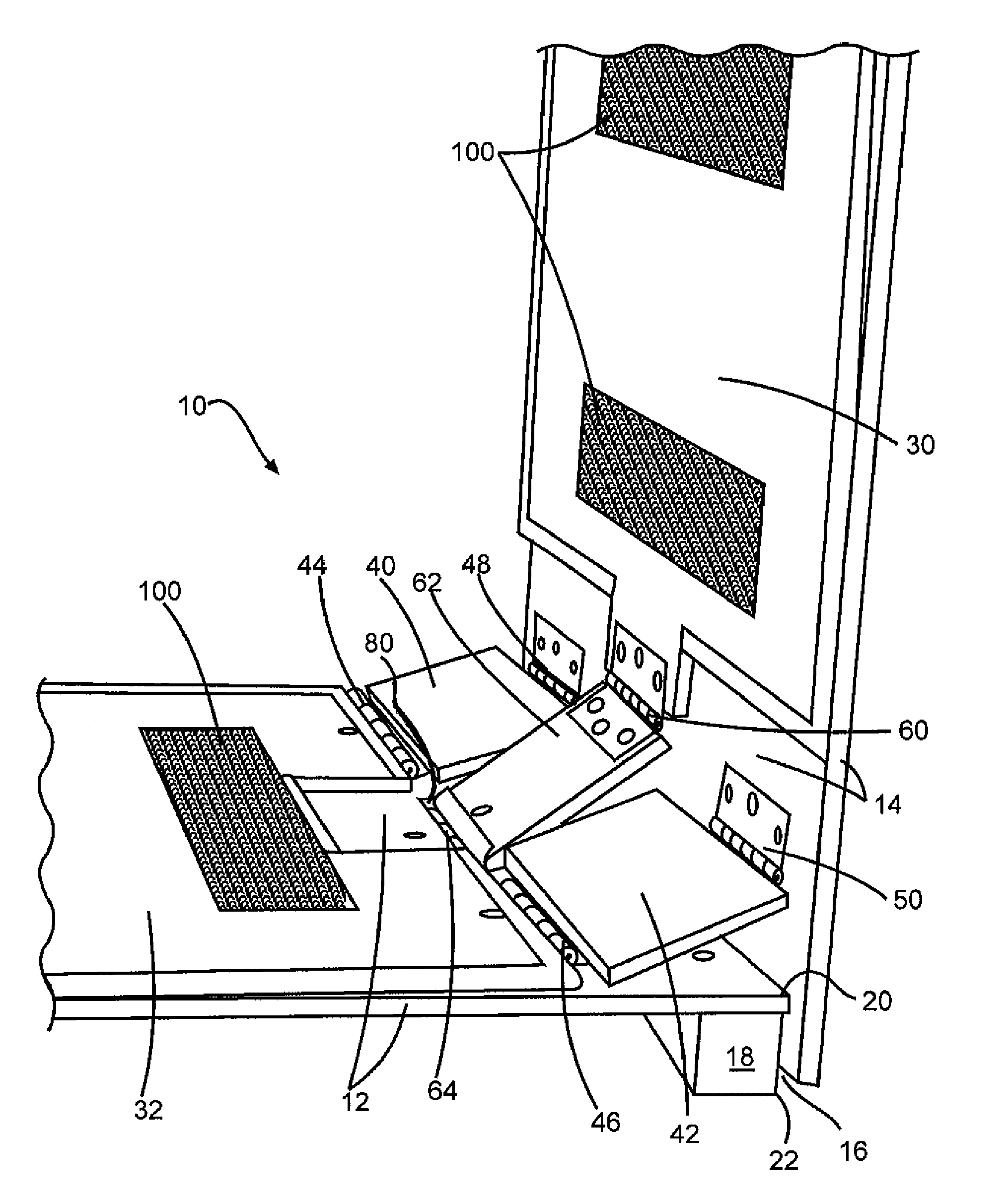
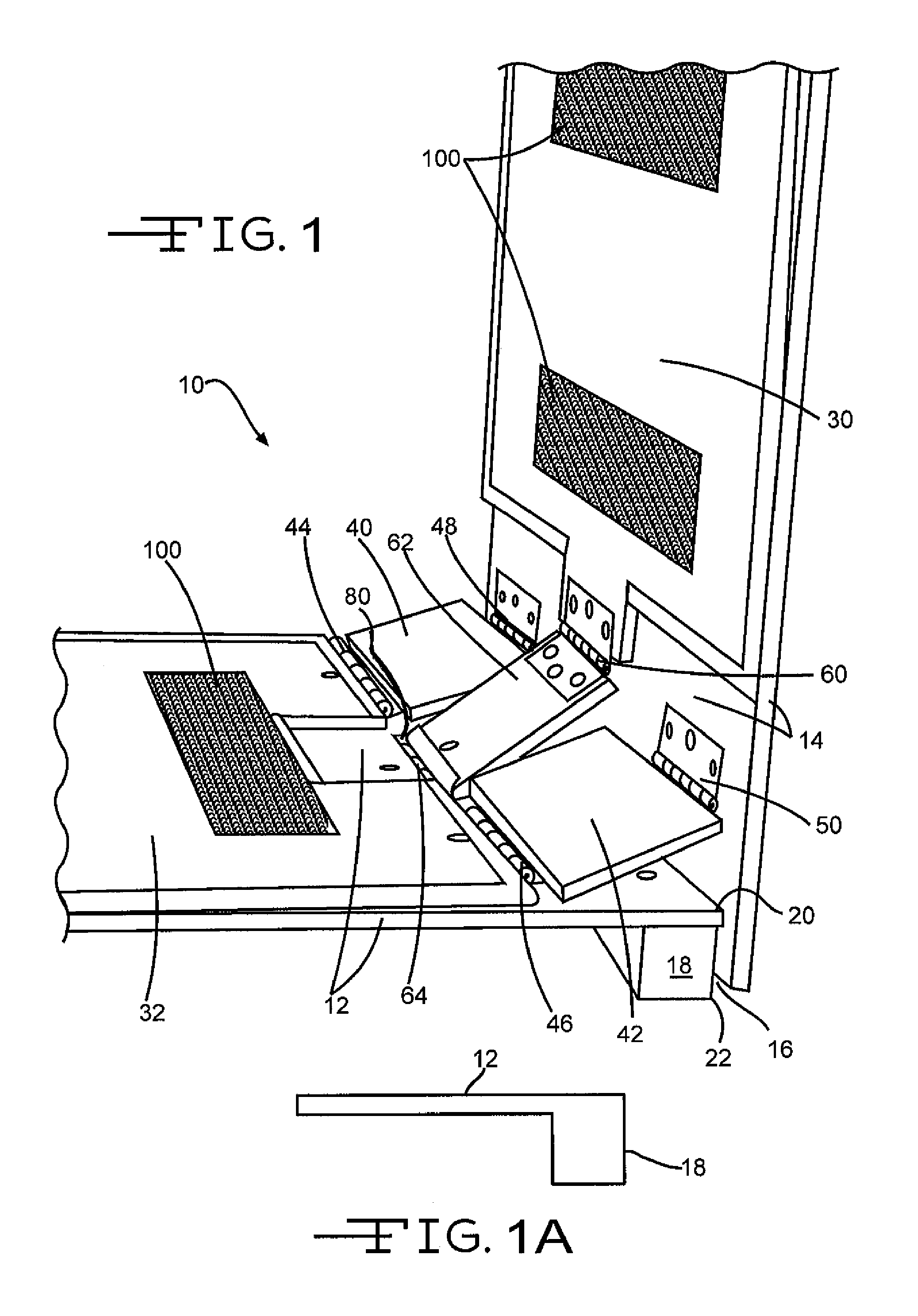
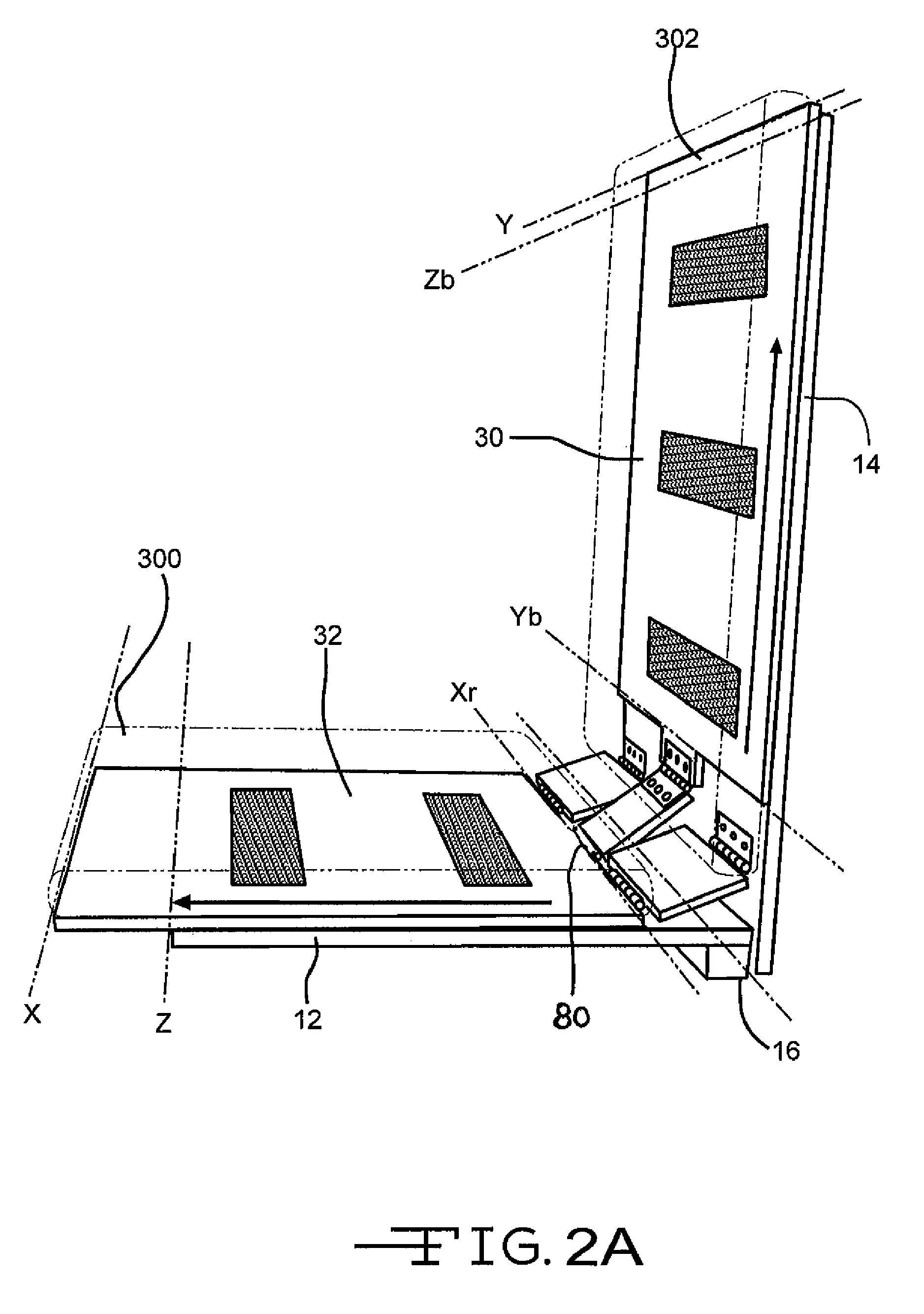
[0015]FIG. 1 illustrates shear reducing apparatus 10 having a seat plate 12 pivotally attached to back plate 14 at point 16 through an offset unit 18. The offset unit 18 is a quarter inch to 3 inch device positioned at the seat plate's proximal end 20. The seat plate's proximal end 20 and the offset unit 18 proximal end 22 can be in the same plane and preferably are. It should be noted that the offset unit 18 can be (a) a separate and distinct piece from the seat plate 12 that is attached to the seat plate 12 or (b) an extension of the seat plate 12 so the seat plate 12 and the offset unit 18 are the same piece as shown in FIG. 1A.

[0016]Positioned over the back plate 14 is a back slide plate 30 and positioned over the seat plate 12 is a seat slide plate 32.

[0017]Back slide plate 30 is attached at hinge point 60 to back transition plate 62. Back transition plate 62 (a) is attached to seat plate 12 at hinge point 64 and (b) positioned within a seat plate opening 80. The hinge point 64...


PUM


Abstract

A device that can be attached to any existing reclining type device such as chairs and beds that will eliminate shear forces on the user's body regardless of the level of movement. The primary components of the device are a seat plate, a seat slide plate, a back plate and a back slide plate. The back slide plate is pivotally attached to the seat plate. The seat slide plate is pivotally attached to the back plate. Pivoting the back plate with respect to the seat plate engages the pivotally attached seat slide plate and the pivotally attached back slide plate toward or away from each other depending on the starting position. The engagement of the slide plates mirrors the movement of the occupant in both the recline to horizontal position or the return to upright to vertical position.

Description

FIELD OF THE INVENTION[0001]The present invention is directed to decreasing and possibly eliminating a patient's skin shear.BACKGROUND OF THE PRESENT INVENTION[0002]Geometrically, the pivot point of an occupant's hip rotation and the pivot point of reclining back are misaligned. As the occupant is positioned in the upright position and then reclined to a horizontal position (or alternatively referred to as a supine position), the distance from the occupant's back and hamstrings contract or decrease. When starting from the horizontal position and moved to the upright position the distance from the occupant's back and hamstrings expands or increases.[0003]Prior patents have addressed only half the problem by developing various systems that allow for a sliding type movement of the back rest. Some of those prior patents include and are not limited to U.S. Pat. Nos. 6,296,265 to Lovins—Oct. 2, 2001; 5,634,688 to Ellis—Jun. 3, 1997; 5,549,357 to Counts et al.—Aug. 27, 1996; 5,261,725 to R...

Claims


Application Information

Patent Timeline
Patent Type & Authority Patents(United States)
IPC IPC(8): A47C1/12
CPCA61G5/1067A47C1/03294A61G2203/74
Inventor HOGG, MARK G.
Owner HOGG MARK G
Why Eureka
Try Eureka