Light emitting module and surface light source device

a light emitting module and light source technology, applied in the field of light emitting modules, can solve the problems of increasing the cost, requiring a larger space for the mixture of light, and the volume of the conventional light emitting module b>100/b> is larger, so as to improve the light emitting efficiency, improve the light guide effect, and increase the intensity

Inactive Publication Date: 2009-02-17
CORETRONIC
View PDF5 Cites 7 Cited by
  • Summary
  • Abstract
  • Description
  • Claims
  • Application Information

AI Technical Summary

Benefits of technology

[0009]Accordingly, an object of the present invention is directed to a light emitting module having a higher light emitting efficiency.
[0013]According to the light emitting module of the present invention, a portion of the light beam provided by the light source set is reflected by the second reflection surface to be reflected to the light emergent surface directly, and the other portion of the light beam is reflected to the first reflection surface and reflected by the first reflection surface, and then the light beam is emerged from the light emitting surface. Since the light guide member has a better light guide effect, which reduces the occurrence of total internal reflections within the light guide member, the light emitting efficiency is improved, such that the surface light source device having the light emitting modules provide a surface light source with higher intensity.

Problems solved by technology

However, this would increase the cost and requires a larger space for mixture of the light, and therefore the volume of the conventional light emitting module 100 is larger.
Additionally, the cost of the LED package structure 120 of side emitting is higher to result in a higher fabrication cost of the light emitting module 100.

Method used


Image

  • Light emitting module and surface light source device
  • Light emitting module and surface light source device
  • Light emitting module and surface light source device

Examples


second embodiment

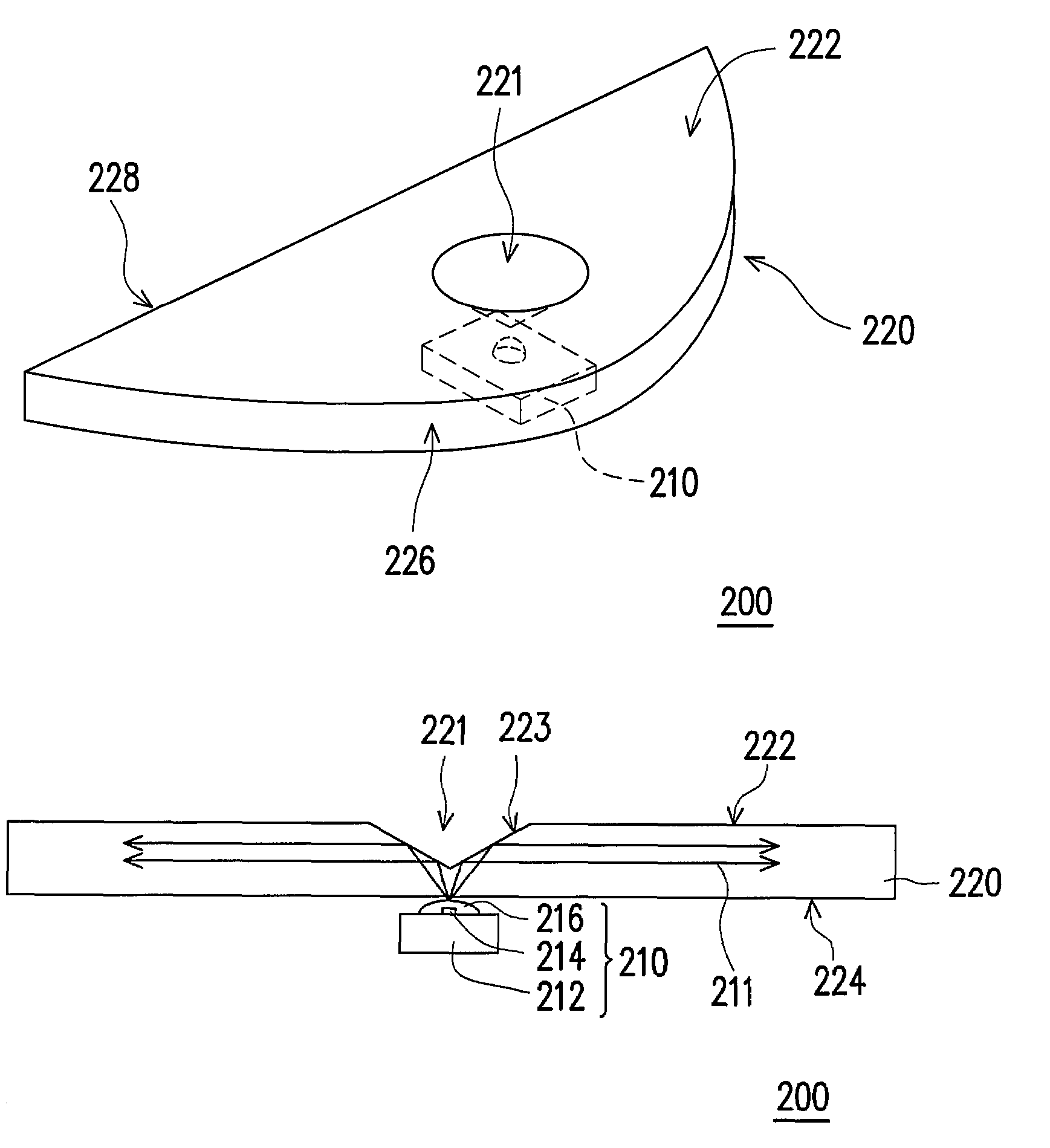
[0030]FIG. 4 is a schematic cross-sectional view showing a light emitting module according to a second embodiment of the present invention. Referring to FIGS. 3B and 4, the light emitting module 200′ of the second embodiment is similar to the above-mentioned light emitting module 200 except that the light incident surface 224 of the light guide member 220′ of the light emitting module 200′ has a second concave surface 229 opposite to the first concave surface 221. The light source set 210 is embedded in the second concave surface 229 to make the alignment of the light source set 210 and the light guide member 220′ be easier and further reduce the assembly time.

third embodiment

[0031]A third embodiment is to apply the light emitting modules 200, 200′ of the first embodiment and the second embodiment to a surface light source device. The surface light source device 300 comprises a light guide plate 310 and a plurality of light emitting modules 200. The light emitting modules 200 are disposed at one side of the light guide plate 310 (as shown in FIG. 5) or both sides of the light guide plate 310 (as shown in FIG. 6) The light beam 211 emerged from the light emergent surface of the light guide member 220 of each light emitting module 200 is incident into the light guide plate 310. The light guide plate 310 is suitable for transferring the light beams 211 into a surface light source with a uniform brightness. The light guide member 220 of each light emitting module 200 is separated or integrally formed, and the light guide member 220 and the light guide plate 310 of each light emitting module 200 are separated or integrally formed. When the light guide member ...


PUM


Abstract

A light emitting module including a light source set and a light guide member is provided. The light source set is suitable for providing a light and the light guide member is disposed above the light source set. The light guide member has a top surface, an opposite light incident surface, a first reflection surface, and an opposite light emergent surface connected between the top surface and the light incident surface. The top surface has a first concave surface serving a second reflection surface suitable for reflecting the light. Besides, a portion of the light reflected by the second reflection surface emerges from the light emergent surface through the reflection of the first reflection surface, and the other portion of the light directly emerges from the light emergent surface. Additionally, a surface light source device having the light emitting module is also provided.

Description

CROSS-REFERENCE TO RELATED APPLICATION[0001]This application claims the priority benefit of Taiwan application serial no. 94146078, filed Dec. 23, 2005. All disclosure of the Taiwan application is incorporated herein by reference.BACKGROUND OF THE INVENTION[0002]1. Field of the Invention[0003]The present invention generally relates to a light emitting module, and more particularly, to a light emitting module using light emitting diodes (LEDs) as a light source and a surface light source device in which the light emitting module is applied to.[0004]2. Description of Related Art[0005]Recently, with an increased in the light emitting efficiency of the LED, the LED has gradually replaced the fluorescent lamp and the incandescent lamp in some fields, such as the backlight module of the liquid crystal display (LCD).[0006]FIGS. 1A and 1B are schematic diagrams showing a side emitting light emitting devices disclosed in the U.S. Pat. No. 6,598,998. The conventional light emitting module 100...

Claims


Application Information

Patent Timeline
Patent Type & Authority Patents(United States)
IPC IPC(8): F21V7/04
CPCG02B6/0018G02B6/0021G02B6/0028G02F1/133603
Inventor LIU, MING-DAHSHIAU, TZENG-KECHOU, WEN-BINHOU, TENG-CHAO
Owner CORETRONIC
Why Eureka
Try Eureka