Fishing lure oscillator

a technology of oscillator and lure, which is applied in the field of fishing lures, can solve the problems of delicate construction of lures regarding weight alignment and distribution, difficulty in making lure dives, and current art falling shor

Active Publication Date: 2009-02-24
PETERSON TIMOTHY GEORGE
View PDF36 Cites 32 Cited by
  • Summary
  • Abstract
  • Description
  • Claims
  • Application Information

AI Technical Summary

Problems solved by technology

The problem with attaching a deflector lip on the trailing end of a plug or crankbait is that it is difficult to make the lure dive, due in part, to the angle of the line.
Another issue with plugs and crankbaits is the delicate construction of the lures regarding weight alignment and distribution.
Not only does the current art fall short in disclosing hardbaits having motion-activating, non-rotating blades mounted on their tail ends, none has been found to disclose a tailpiece that imparts an up and down oscillation resembling that of a dying minnow lying on its side.
In turn, many lures over the years have been introduced, attempting to emulate that particular action, but have realized very little success.
Insofar as the current art is able, it has not disclosed a commercially viable or suitable plug, crankbait, or jig with the versatility to swim with a tailpiece that can be adjusted to produce either a side to side or an up and down oscillation.
Further, it has not disclosed a deflector-type lure device that can be attached to most lure types in a vertical or horizontal orientation.
Although a substantial amount of resistance creates an action on these lures, the disposition of such pieces do not allow for a stable swimming posture of the lure wherein the lure will roll on its side, or it will not swim at a consistent depth.
Most of the prior art motion devices are integral to a lure and are not interchangeable with other lure types, nor are they designed to do so.
Others are superfluous in design and construction resulting in relatively complex mechanisms, and thus, contributing to higher material, labor, and manufacturing costs.

Method used


Image

  • Fishing lure oscillator
  • Fishing lure oscillator
  • Fishing lure oscillator

Examples


Embodiment Construction

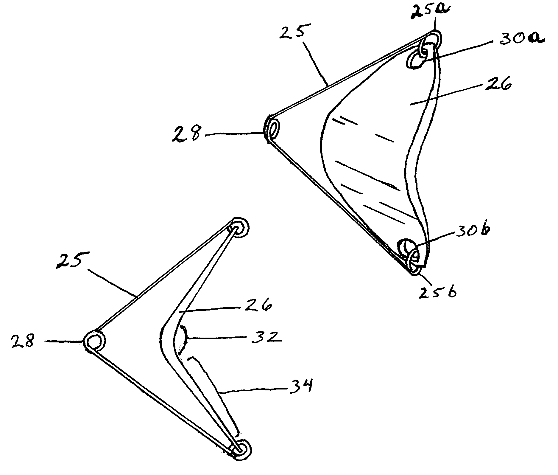
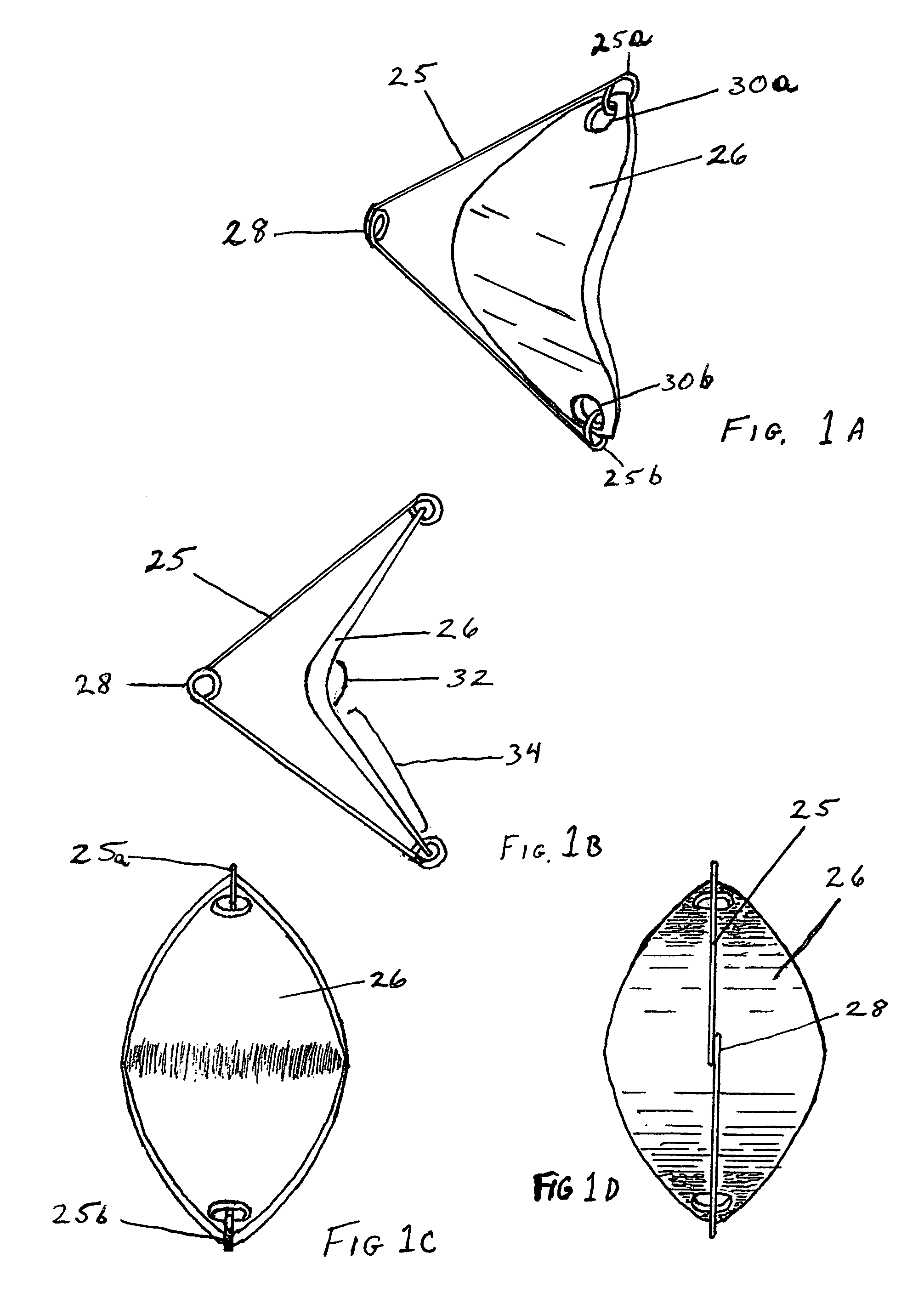
[0037]A preferred embodiment of the invention is illustrated in different views in FIGS. 1A-1D. FIG. 1A is a perspective view, FIG. 1B is a side view, FIG. 1C a rear view, and FIG. 1D a front view.

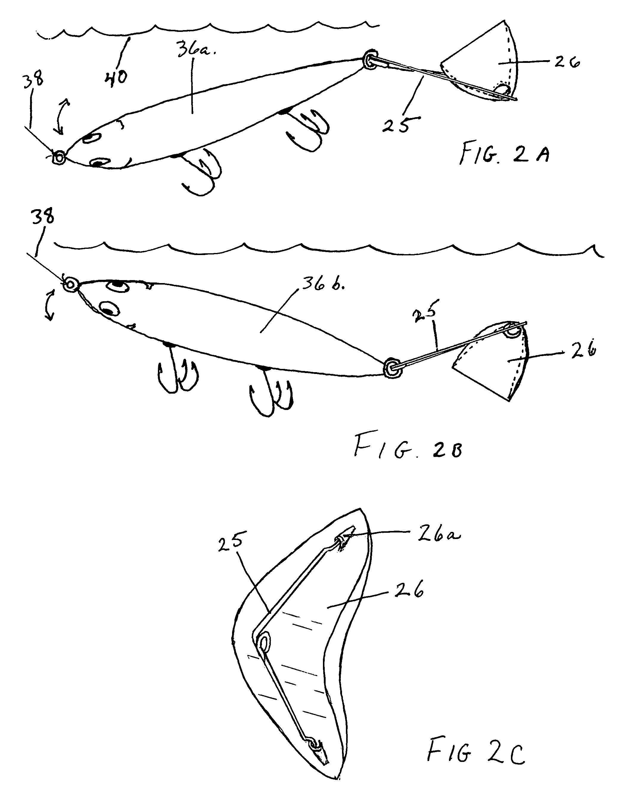
[0038]The fishing lure oscillator in the embodiment comprises a frame 25 formed from a safety pin coil spring formation hereinafter referred to as “connector”28. Connector 28 is used as a pivotal attachment device that connects the frame to a fishing lure or fishing line. Two appendages of frame 25 branch out from connector 28 giving the frame a substantially v-shaped configuration with the connector defining an apex of the v-shaped frame. Each appendage terminates at closed loops 25a and 25b. The frame and loops are integrally formed from a single length of relatively stiff stainless steel wire. Each appendage forms a somewhat straight line from the apex to the loops, but can also be formed with a bend or curve.

[0039]The angle of frame 25 formed by the diverging appendages has minimal lim...


PUM


Abstract

A fishing lure oscillator, comprising a bent, oblonged, essentially elliptical foil having relatively uniform thickness. Near one end of the foil, a connection is made to an appendage, and near the opposite end of the foil a connection is made to another appendage. Both appendages, serving as a framing device to support the foil, originate from a common base which is adapted to be joined with a fishing lure. When joined with a lure and pulled through a body of water, an outwardly contoured portion of the foil is disposed directly against the flow of water whereby the force of water against the resisting face of the foil causes the foil to pivot freely within the framing device, thus transferring the resulting oscillation to the lure for the purpose of attracting and catching fish.

Description

CROSS REFERENCE TO RELATED APPLICATIONS[0001]This application claims the benefit of provisional patent application Ser. No. 60 / 659,023 filed 2005 Mar. 5, by the present inventorFEDERALLY SPONSORED RESEARCH[0002]Not ApplicableSEQUENCE LISTING[0003]Not ApplicableBACKGROUND OF THE INVENTION[0004]a. Field of Invention[0005]The present invention pertains generally to fishing lures and other devices such as flashers, dodgers, and trolling rigs, and specifically to fishing lure accessories that are coupled with fishing lures for the purpose of enhancing fish-attracting oscillation.[0006]b. Description of the Background[0007]Fishing lures are made in a myriad of shapes, sizes, weights, colors, functions, materials, and types to attract fish and, individually, are generally confined and dependent upon specific means to simulate the swimming motions of real fish: various weight placement in their bodies; or water deflecting blades positioned in the front to resist water causing the lure to wo...

Claims


Application Information

Patent Timeline
Patent Type & Authority Patents(United States)
IPC IPC(8): A01K85/00
CPCA01K85/00A01K85/10
Inventor PETERSON, TIMOTHY GEORGE
Owner PETERSON TIMOTHY GEORGE
Why Eureka
Try Eureka