Wiper blade for cleaning screens in particular on motor vehicles

a technology for cleaning screens and motor vehicles, applied in vehicle cleaning, domestic applications, vehicle maintenance, etc., can solve the problems of increasing the weight of the wiper blade in an undesirable fashion, requiring a relatively large amount of material, and the use of a large amount of material

Inactive Publication Date: 2002-09-26
ROBERT BOSCH CORP
View PDF4 Cites 44 Cited by
  • Summary
  • Abstract
  • Description
  • Claims
  • Application Information

AI Technical Summary

Problems solved by technology

The triangular profile used requires a relatively large amount of material for the manufacture of the wind-deflection strip, which is reflected in the costs for the wiper blade.
Moreover, the weight of the wiper blade is considerably increased in an undesirable fashion.
Namely, the increased mass, which must be accelerated in the

Method used


Image

  • Wiper blade for cleaning screens in particular on motor vehicles
  • Wiper blade for cleaning screens in particular on motor vehicles
  • Wiper blade for cleaning screens in particular on motor vehicles

Examples


Embodiment Construction

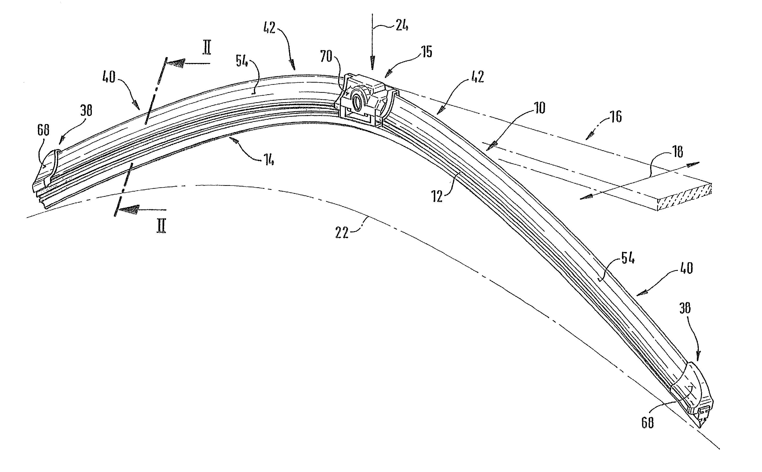
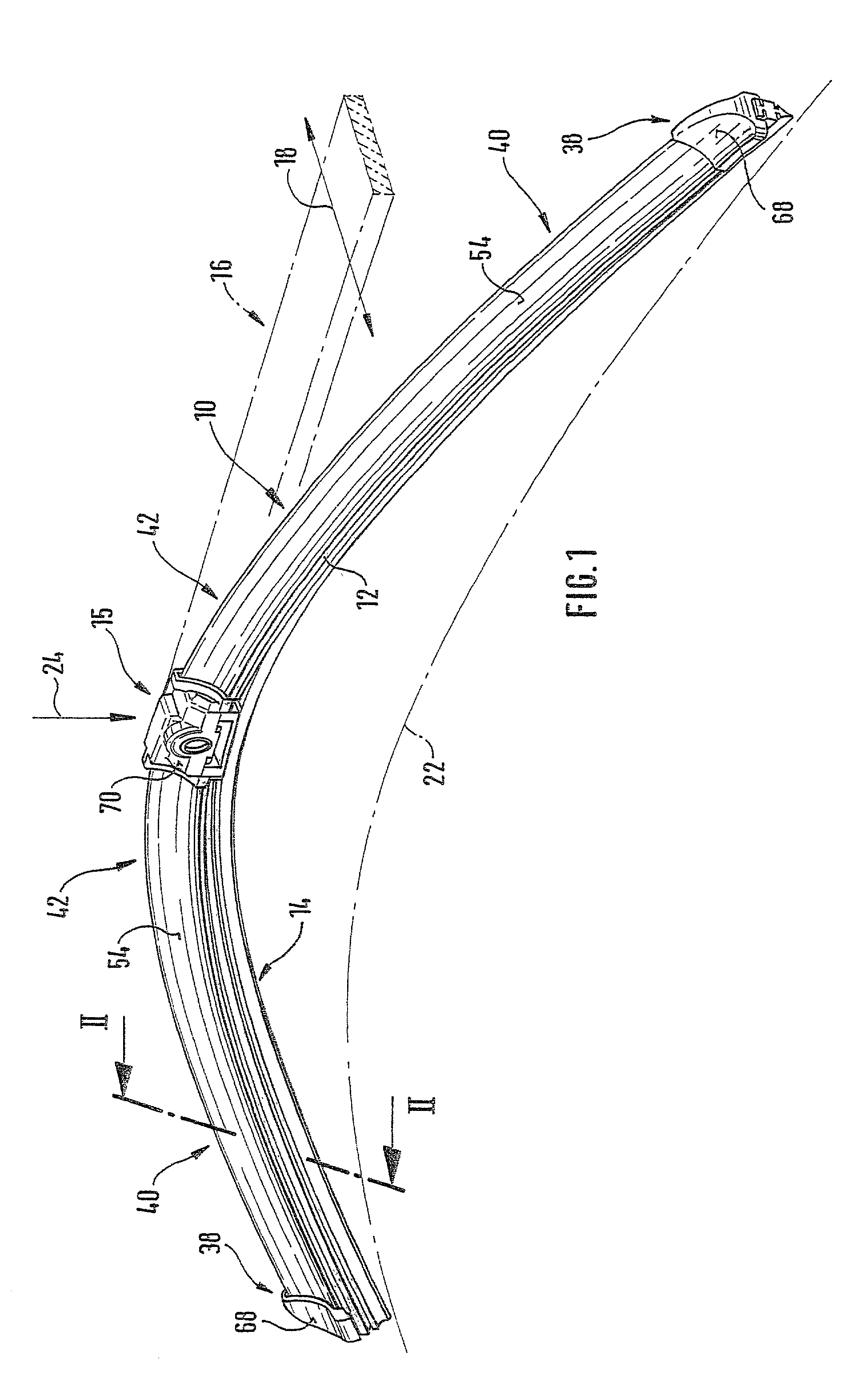
[0031] A wiper blade 10 shown in FIG. 1 has a band-like, elongated, spring-elastic support element 12 (FIGS. 1 and 2), whose lower band side 13 oriented toward the window has an elongated, rubber-elastic wiper strip 14 attached to it so that the longitudinal axes of these two parts are parallel. On the upper band side 11 of the support element 12, which is oriented away from the window, which support element is also referred to as a spring strip, the middle section of the support element is provided with the wiper blade part 15 of a connecting device, with the aid of which the wiper blade 10 can be detachably connected in an articulating fashion to a wiper arm 16 indicated with dot-and-dash lines in FIG. 1. The wiper arm 16, which is driven to reciprocate in the direction of a double arrow 18 in FIG. 1, is loaded in the direction of an arrow 24 toward the window to be wiped, for example the windshield of a motor vehicle, whose surface is indicated with a dot-and-dash line 22 in FIG....


PUM


Abstract

A wiper blade for cleaning motor vehicles is proposed, which is provided with a band-like, elongated, spring-elastic support element (12). The lower band surface (13) of the support element (12) oriented toward the window (22) has an elongated, rubber-elastic wiper strip (14), which can be placed against the window (22), disposed on it so that the longitudinal axes of these two parts are parallel and the upper band surface (11) of the support element (12) has a wind deflection strip (42) disposed on it, which extends in the longitudinal direction of the support element, is provided with an attack surface (54) oriented toward the main flow of the relative wind, and is comprised of an elastic material. A considerable weight savings for the wiper blade is achieved if the wind deflection strip (42, 142, or 242) has two diverging legs (44, 46), viewed in cross section, which are connected to each other at a common base (48) and whose free ends (50, 52) oriented toward the window (22) are supported on the wiper blade (10), and the attack surface (54) is embodied on the outside of the one leg (44).

Description

PRIOR ART[0001] In wiper blades of the type described in the preamble to claim 1, the purpose of the support element is to assure as uniform as possible a distribution of the wiper blade pressure against the window, which pressure is exerted by the wiper arm, over the entire wiping field wiped by the wiper blade. Through an appropriate curvature of the unloaded support element--i.e. when the wiper blade is not resting against the window--the ends of the wiper strip, which is placed completely against the window during operation of the wiper blade, are loaded toward the window by the support element, which is stretched in this state, even though the curvature radii of spherically curved vehicle windows change with each wiper blade position. The curvature of the wiper blade must therefore be somewhat sharper than the sharpest curvature measured within the wiping field on the window to be wiped. The support element consequently replaces the expensive support bracket structure with two ...

Claims


Application Information

Patent Timeline
IPC IPC(8): B60S1/38
CPCB60S1/381B60S1/3879B60S1/3894
Inventor DE BLOCK, PETERWIJNANTS, PETER
Owner ROBERT BOSCH CORP
Why Eureka
Try Eureka